

It is not necessary to measure the current at the shunt resistors on the board. The code logic works out the percentage of maximum power and uses that to calculate the required pulse width, saving cpu time.It wouldn't surprise me if your controller can't even measure phase current. Instead, it measures the battery current and derives some number based on an arbitrary calculation.
Let's say your motor is running at 200 rpm, has a reduction ratio of 8:1 and 12 poles. That would mean that each phase has 200 x 8 x 12 main pulses per minute in both forwards and backwards directions, which is 640 pulses a second. That's almost simple because the only problem is whether you want to measure a forward pulse, a backward one or both together. The net current from both is zero. It's a bit like A/C. You could count an RMS value or anything like that, but at what speed are you going to measure it because the motor speed could be anything between zero and 200 rpm.
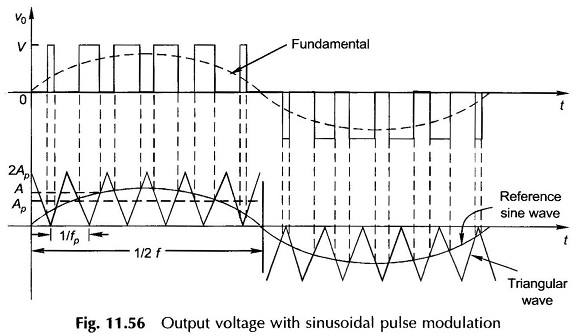
Now it gets complicated because you have sinewave pwm controller. Each of those 640 pulsesa second is divided into say ten steps, which have a duty cycle of between zero and 100%. Obviously, the current would be half as much if the duty cycle was 50% compared with 100%, but your controller is a sinewave one, so the first and last step have a small duty cycle and the middle ones have a large one. The change in width over the ten steps follows a sinewave. Now tell me at any point in time how you're going to define current.
Here's a picture to help you visualise. What's shown happens 640 times a second:
Last edited:
