Lishui Controller Modification - Firmware Flash Project

Sparksandbangs

Pedelecer
Jan 16, 2025
157
49
I’ve had the urge to tinker with firmware for ages and have decided to take the plunge.

As I want to use the bike while I'm experimenting this necessitates purchasing another controller for testing purposes. Options are another KT sinewave controller and flash with OSEC firmware or a Lishui controller which arguably has better hardware than the KT and flashing with eBics. The settings will then be modified to mimic the standard KT controller but hopefully in a better package.

After reading through the procedures for both controllers the KT appears easier to set up than the Lishui. The Lishui also has the added problem (for me) that the forum discussing it is a German language forum. Google translate can only get you so far and it makes it difficult to search for specific terms in a monster length thread if you don't speak the language.

In the pioneering spirit I have of course gone for the more difficult option on the hope it will give me a better outcome.

There is a Wiki in English

First thing order a controller. This is one of them recommended in the Wiki for the project.

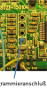
First issue. On opening it up it has been potted with some grey goo. Not quite the consistency of silicone sealant and not quite decorators calk but somewhere in between. After removing both end caps and the 3 screws holding the MOSFET rail a bit of light pressure on it reveals it to be stuck in the case. A bit of exploratory digging reveals the aluminium rail running through the controller with all the MOSFETs attached to it. With the case held in the vice and a small length of wood thinner than the case placed on the rail followed by couple of short, sharp taps with a lump hammer the circuit board pops out. Aluminium bar is pictured below on a photo borrowed from another forum. I have added a red circle to show the point to whack.

63730

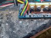
Now needs a bit of digging to clean it up to reveal the board.

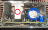
Next problem. There is no throttle connection. I hadn't noticed when I ordered it. A quick look at the chip drawing shows that a wire should be soldered from 'SP' on the board. A lead from the ground and another from the +5v rail adds the throttle function.
 
  • Like
Reactions: Jodel

Sparksandbangs

Pedelecer
Jan 16, 2025
157
49
And the next problem I can identify the programming port but terminals are not identified. An internet search suggests the configuration below:
63731

Testing with a multimeter confirms the +3.8v and ground. Soldered leads as below:

63732

Next problem. PAS is x 5 wire connection.

This is because the controller is designed to be used with a bottom bracket torque sensor. I just want to use a normal magnetic PAS. The voltage output is 15v, I doubt that will work well with my sensor so use the 5v and ground from the throttle. There are two pas wires. One is an inverse PAS signal. My guess is this is the one to use with a left hand sensor, the other two signal wires are for the PAS normal sensor and the torque sensor that I won’t be using.

With the first steps completed it is now time to connect to the bike and test what happens with stock firmware.

First test using stock firmware. Wheel off the ground using walk assist from the display - working.

Throttle - nothing. Maybe it isn't activated in the stock firmware. A quick check with a multimeter shows that voltages are as expected.

PAS - nothing. I could have this wired up incorrectly. I could try swapping it to the other PAS input wire.


Think I may just flash a basic version of eBics from the java tool and try the test again.
 

Sparksandbangs

Pedelecer
Jan 16, 2025
157
49
Followed the instructions from the Wiki. Connected ST-Link V2. Opened the Java tool. Set up the battery levels, switched off torque sensing. Set the speed limit and set to debug. Clicked on the enable autodetect in debug mode.

63733

Unlocked controller then flashed. Error 30 is now showing on the controller

Unplugged ST-Link V2. Switched off, wheel off the floor, switched back on again and autodetect cycle runs to completion. Bit of knocking and banging noises coming from the hub.

Plugged ST-Link V2 back in and reflashed. Now out of debug mode and back to using the EN06 display.

Powered up and throttle and PAS now work. The throttle must have been disabled in stock firmware.

First success.
 
  • Informative
Reactions: Jodel

Sparksandbangs

Pedelecer
Jan 16, 2025
157
49
I’ve tweaked the code in Eclipse. Fairly sure that I’ve set up all the parameters correctly. Changed the display to the LCD3.

Go to flash to the controller and it fails every time. Strangely if I try to flash from the Java tool it works. Unfortunately the Java tool doesn’t allow in depth changes.

Tried changing multiple settings to get it to flash from Eclipse but doesn’t make the blindest bit of difference. Then in a eureka moment realised that the Java tool flashes using the command line.

Complied the code in Eclipse then flashed from the command line. Worked perfectly. Not an ideal solution but I’ll go with it.

Mounted the controller on the bike ready for a test run.


PAS Level 1. Start pedalling and a longer delay than I’m used to and the thing sets off like a rocket. It appears that my attempts to recreate the KT assist levels have not gone to plan. Various other little niggles. Realise that I should have changed one thing at once and got it working instead of doing the whole lot in one.

Test the throttle and strangely works with the assist set at 0. The speed goes up to 6kmph and cuts off. Pedal and press the throttle and full power applied. Interestingly unlike the KT the throttle isn’t an on off switch it works like a throttle with a graduated application of power.


Now I’ll have to look at the coding. Undo all the changes that I’ve made and focus on one thing until I get it right and then move on to the next. First priority is sorting out the assist levels.


I now have to disassemble the controller housing every time that I want to flash the controller. I realise this is going to get tedious very soon. I’m going to have to solder on some sort of flying programming lead to address this.
 

Woosh

Trade Member
May 19, 2012
21,354
17,324
Southend on Sea
wooshbikes.co.uk
My programmer connects to the 5 pin LCD. Hardwarewise, it looks like an ST-Link V2.
 

AndyBike

Esteemed Pedelecer
Nov 8, 2020
1,710
732
Fiddling about with electrical systems.

Username checks out ... :D
 

Sparksandbangs

Pedelecer
Jan 16, 2025
157
49
My programmer connects to the 5 pin LCD. Hardwarewise, it looks like an ST-Link V2.
I have a FT232 USB UART Board but unfortunately it was unsuccessful when I tried to flash through the display connector. It's taken days of experimenting and I'm just pleased that something works.
 
  • Like
Reactions: Woosh

guerney

Esteemed Pedelecer
Sep 7, 2021
12,124
3,386
Lishui Controller Modification - Firmware Flash Project
I'm following this fun looking project. Interested to know why you selected Lishui over KT.

Tried changing multiple settings to get it to flash from Eclipse but doesn’t make the blindest bit of difference. Then in a eureka moment realised that the Java tool flashes using the command line.

Complied the code in Eclipse then flashed from the command line. Worked perfectly. Not an ideal solution but I’ll go with it.
Perhaps command line allows run as Administrator?
 
Last edited:

Sparksandbangs

Pedelecer
Jan 16, 2025
157
49
I'm following this fun looking project. Interested to know why you selected Lishui over KT.
Lishui controllers have better hardware. They are smaller with a more powerful processor.
The stock software in the KT is better for the end user but since I'm overwriting it I figured that I might as well go for the Lishui. When I get it working I might experiment with flashing the KT just to see what happens.

Perhaps command line allows run as Administrator?
I think it has something to do with the settings in Eclipse. Using the command line works so I'm not going to spend too much time trying to solve it. Priority is to get a usable bike that doesn't launch itself down the road like a rocket in Level 1 assist.
 
  • Like
Reactions: Woosh

Sparksandbangs

Pedelecer
Jan 16, 2025
157
49
Looking at my coding last night for the assist it suddenly becomes clear what I've done. In the original code for using an LCD3 it just divides the output into fifths. L1 is 20%, L2 is 40% etc. The Bafang display code has an assist factor allowing more accurate mapping. In attempting to add this to the KT code I accidentally multiplied it to a number greater than 1 meaning it was delivering full power in all assist levels. This is now corrected.

First proper run this morning. Assist levels work like the KT with L1 at 13% and all the way through to L5 at 100%. Pickup for pedal assist seems to have a delay. So I will have to look at that. I might be imagining it but it seems the faster you pedal, the more power is delivered.

The power delivered is more than the KT so it will need to be reduced to give a fair comparison.

Speed sensing is all over the place. When freewheeling it drops to a silly number and when over cut off it freezes at the cutoff point. I guess it is picking it up from the Hall sensors rather than the speed pickup.

Overall though a promising start. Will ride it for a few more days without modifying to see if I can pickup on anything else that needs changing.
 

saneagle

Esteemed Pedelecer
Oct 10, 2010
8,928
4,000
Telford
Looking at my coding last night for the assist it suddenly becomes clear what I've done. In the original code for using an LCD3 it just divides the output into fifths. L1 is 20%, L2 is 40% etc. The Bafang display code has an assist factor allowing more accurate mapping. In attempting to add this to the KT code I accidentally multiplied it to a number greater than 1 meaning it was delivering full power in all assist levels. This is now corrected.

First proper run this morning. Assist levels work like the KT with L1 at 13% and all the way through to L5 at 100%. Pickup for pedal assist seems to have a delay. So I will have to look at that. I might be imagining it but it seems the faster you pedal, the more power is delivered.

The power delivered is more than the KT so it will need to be reduced to give a fair comparison.

Speed sensing is all over the place. When freewheeling it drops to a silly number and when over cut off it freezes at the cutoff point. I guess it is picking it up from the Hall sensors rather than the speed pickup.

Overall though a promising start. Will ride it for a few more days without modifying to see if I can pickup on anything else that needs changing.
KT uses two speed signals for different functions. Speed sensor is used for the LCD, assuming a non-zero speed sensor setting, and the halls are used for the max speed cut-off.
 

Sparksandbangs

Pedelecer
Jan 16, 2025
157
49
KT uses two speed signals for different functions. Speed sensor is used for the LCD, assuming a non-zero speed sensor setting, and the halls are used for the max speed cut-off.
On checking the speed source is set to internal. Which is why it is coming from the halls.

I'm not sure whether or not this controller works in the same way you have described. I could set it to internal, disconnect the speed sensor wire and see what happens.
 

Sparksandbangs

Pedelecer
Jan 16, 2025
157
49
Changed the speed source to internal and disconnected the white speed signal wire. No reading on the display but that is not unexpected. Power delivered all the time and no limit in force so it is either one or the other not a blend of both like the KT controller

Problem is that with the white wire connected I get no reading on the display. Spun the wheel by hand with the multimeter between the white and ground and get 3.4V constant (thought this was a bit low, expected around 4.3V) with a flicker on the multimeter when passing the same point of rotation. Realise that I should have checked the voltage from the controller speed sensor wire and then tried shorting it to ground to see if I could generate a pulse. Will try that later.

Used a long motor extension cable and connected the motor to my other bike with a standard KT controller and spun the wheel. Shows a speed signal on the other bikes display. Will have to try the opposite and connect the other bikes motor (also an AKM) to the modified controller and see what happens. I have a Bafang hub hanging in the shed so might try with that as well as a comparison between makes.

If none of these work I could try an external sensor (will have to order one) to test. If that doesn't work it might be coding which is beyond my tinkering knowledge so might have to as for help elsewhere to understand and solve the problem.
 
Last edited:

Sparksandbangs

Pedelecer
Jan 16, 2025
157
49
Nearly forgot. Did some soldering to firm up some of the connections and restock my box of spare Wago connectors. Soldered in a 4 pin Julet connector to the programing port so now I don't have to take the controller case apart to flash any changes.
 

saneagle

Esteemed Pedelecer
Oct 10, 2010
8,928
4,000
Telford
Changed the speed source to internal and disconnected the white speed signal wire. No reading on the display but that is not unexpected. Power delivered all the time and no limit in force so it is either one or the other not a blend of both like the KT controller

Problem is that with the white wire connected I get no reading on the display. Spun the wheel by hand with the multimeter between the white and ground and get 3.4V constant (thought this was a bit low, expected around 4.3V) with a flicker on the multimeter when passing the same point of rotation. Realise that I should have checked the voltage from the controller speed sensor wire and then tried shorting it to ground to see if I could generate a pulse. Will try that later.

Used a long motor extension cable and connected the motor to my other bike with a standard KT controller and spun the wheel. Shows a speed signal on the other bikes display. Will have to try the opposite and connect the other bikes motor (also an AKM) to the modified controller and see what happens. I have a Bafang hub hanging in the shed so might try with that as well as a comparison between makes.

If none of these work I could try an external sensor (will have to order one) to test. If that doesn't work it might be coding which is beyond my tinkering knowledge so might have to as for help elsewhere to understand and solve the problem.
Some controllers require a high pulse, others require a low pulse from the speed signal. You have to experiment to see what works.
 

Advertisers