Reduce Charger Voltage

awol

Esteemed Pedelecer
Sep 4, 2013
1,216
374
I bought 25.2v 2a cc/cv charger/powersupply for a simple way to charge my 6s lipo batteries when away from home. Since it was cheap I'd better test it as at 25.2v my cells would need to be perfectly balanced.
I have found it to be 25.4v !!! This is no good but tried it anyway.
When my cells got to 4.21 and 4.22 I gave up and discharged them.
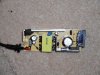
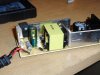
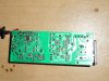
I opened the unit up to look for any variable controls to turn down but there isn't one.
Is there a way to reduce the voltage by about 0.5v down to around 24.9/25v by adding a variable control or resistor or something, maybe check the spec of a part?
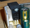
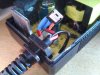
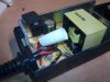
Here are pics of the circuit board -
DSCN0226.JPG DSCN0227.JPG DSCN0228.JPG
 
  • Informative
Reactions: LeighPing

Alan Quay

Esteemed Pedelecer
Dec 4, 2012
2,351
1,076
Devon
Those numbers are pretty close to what you are looking for. Are you sure of the accuracy of your meter? Presumably you'd be happy with 4.2v, but not with 4.23v, an error of 0.15% on the 20v range? Its a similarly small error on the total voltage, 0.1% on the 200v range.
 
Last edited:

anotherkiwi

Esteemed Pedelecer
Jan 26, 2015
7,845
5,785
The European Union
You really need a 24.9 V charger if you want to keep your Lipos happy. I charged to 4.2 V per cell the first few times but after having read heaps of pages on Lipo now charge to 4.15 V. There really isn't a lot of energy in that extra 0.05 V so it doesn't affect your range much at all. And I now have Lipo alarms that ring at 3.65 V instead of the very basic ones which were only accurate to the tenth of a Volt.
 

awol

Esteemed Pedelecer
Sep 4, 2013
1,216
374
Those numbers are pretty close to what you are looking for. Are you sure of the accuracy of your meter? Presumably you'd be happy with 4.2v, but not with 4.23v, an error of 0.15% on the 20v range? Its a similarly small error on the total voltage, 0.1% on the 200v range.
I tried a couple of different cell meters while it was charging to confirm and started sweating when they were flicking up to 4.22v. I also thought about it being within a tolerance so cannot complain to the supplier and decided I wanted it just under 25v if possible by adding/changing a part.
 

Danidl

Esteemed Pedelecer
Sep 29, 2016
8,610
12,256
73
Ireland
I tried a couple of different cell meters while it was charging to confirm and started sweating when they were flicking up to 4.22v. I also thought about it being within a tolerance so cannot complain to the supplier and decided I wanted it just under 25v if possible by adding/changing a part.
If you are uncomfortable with the output voltage from this charger, you can reduce it by 0.7v very simply by inserting a power diode in series with the output. Cut the red output lead at a convenient place and solder a power diode from the 1N 4000 seriesor or 1N5000 series into the lead. The cathode or end with the silver band should face outwards towards the battery. The voltage rating of the diode will not matter as even the lowest is more than adequate, however the current rating needs to be ok. A single 1N4000 diode is capable of 1 amp so you might need to put a few in parallel
 
  • Informative
Reactions: awol
D

Deleted member 4366

Guest
A schottky diode will cut down the voltage a bit less - something like 0.5v. Here, its voltage rating is important, so is its current rating and cooling, so get one that's over-rated.

http://www.ebay.co.uk/itm/DIODE-SCHOTTKY-2X6A-100V-Part-No-VS-12CWQ10FNPBF-By-VISHAY-FORMERLY-I-R-/390997432254?hash=item5b094357be:g:ZD8AAOSwQJhUhe5L

Maplin will have them too, but you have to check the forward voltage (voltage drop) in the specification as well as the current rating and the reverse voltage (blocking) rating.
 
  • Informative
Reactions: awol

awol

Esteemed Pedelecer
Sep 4, 2013
1,216
374
Thanks for those great replies.
Am going to try schottky diode first with it's smaller -0.5v drop and started to research how to wire/solder it in. This made me discover there is one already on there Part Num MBR20200CT 200v 20A
Is there a way to check this one is within spec or could I simply replace it for another maybe higher spec one?
scottky diode.PNG
 
D

Deleted member 4366

Guest
I think that one is being used as a rectifier to convert AC from the transformer to DC for charging. Just put one in the positive charge wire pointing in the right direction.
 

Danidl

Esteemed Pedelecer
Sep 29, 2016
8,610
12,256
73
Ireland
Thanks for those great replies.
Am going to try schottky diode first with it's smaller -0.5v drop and started to research how to wire/solder it in. This made me discover there is one already on there Part Num MBR20200CT 200v 20A
Is there a way to check this one is within spec or could I simply replace it for another maybe higher spec one?
View attachment 16994

D8veh is correct ... Do not touch the components currently on the PCB ... There are no spares there......
If you acquire a 3amp silicon diode with wire terminals you will not even need to solder anything. The standard screw connector strip as used by electricians and available in any hardware shop, even corner shops will do the business . I call these chocolate block connector s because they look like a single row of segments in a cadbury bar. Take two connections. Connect the diode between them cut the red output lead bare the cut ends and insert each into the two other parts of the terminal and screw the terminals tight. Remember that the silver end of the diode should connect to the lead going away from the charger and towards the battery.
Silicon diodes are versitle devices .. when a lot of current is charging the battery, it might drop 1.0v across it. when the battery is nearly charged and the current is moderate the volt drop will be 0.7 and when it is virtually full the voltage drop will cover down to 0.5 V 0.6 V . That will met your requirement . Diodes can be got In. Maplins s or in the power supply of a dead computer. .. just look online for image s of what they look like.
 
Last edited:
  • Informative
Reactions: awol

awol

Esteemed Pedelecer
Sep 4, 2013
1,216
374
I ordered a couple of each type of diodes and the schottky has arrived first so have soldered it in like this - from the pcb to an outer leg, then the middle stub to the outgoing cable and that reduces the volt's about 0.2v which is pretty much good enough.
Does this look safe to use long term with the cover glued back on?
IMG_20161231_130806.jpg
 
D

Deleted member 4366

Guest
No. Make sure that the metal back can't touch anything.I think it's connected to the middle leg, so needs insulating.
 

awol

Esteemed Pedelecer
Sep 4, 2013
1,216
374
Thanks d8veh, a bit of heatshrink should shrink itself on and hopefully won't over heat.
It has an unused leg, was I supposed to connect both outer legs to the pcb?
IMG_20161231_142551.jpg
 

Advertisers