Help! Repair Crystalyte 36 Volt 20A Controller

ralphius

Finding my (electric) wheels
Mar 2, 2019
6
0
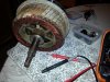
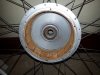
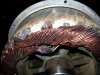
I bought my first ebike kit 2nd hand last year and I've been using it every day to commute to work and love it to bits. The kit consists of a 36V 9Ah battery, Crystalyte 408 motor and Crystalyte 36V 20A "Journey" controller.

Unfortunately it let me down this week, the motor started stuttering (although the power LED's on the throttle still stayed bright without flickering) and then the motor cut out completely and hasn't worked since.

I did some tests this morning, here's what I've done so far:
-tested battery voltage. 40V from the 36V nominal lithium ion, so battery isn't flat
-also have voltage at controller side of anderson connector between battery and controller so not that
-unplugged PAS sensor, brake cutout, 3 mode power level switch, battery gauge etc so I just have battery, controller, thumb throttle + motor. No change.
-have swapped throttle for replacement throttle, not that
-unplugged and cleaned motor phase connector, not that
-unplugged and cleaned motor hall sensor connector, not that
-connect battery directly to each motor phase briefly and wheel moves each time, so motor windings are ok, not that
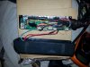
-took apart controller case and identified the hall sensor wires. Voltage between red and black wire fluctuates constantly between 0.6 and 13 volts. Ummm I expected this to be constant, probably 5V?

Anybody know much about these controllers? Photo is of my controller, hall wires are the plug on the far left. Any idea what I can try next?
 

Attachments

vfr400

Esteemed Pedelecer
Jun 12, 2011
9,822
3,985
Basildon
All controllers work more or less the same, so you can replace it with any one. It's always best to buy the controller and the LCD control panel as a pair.

Cyrystalyte are still in business and they have a European shop, though very expensive.

Before commencing, you should confirm that your controller is faulty. Measure the resistance between ground and each of the phase wires. All three results should be similar. Repeat between the red battery wire and each phase wire. Each result should be similar. For these measurements, you might get a changing result, but all should change in a similar fashion.

These tests confirm whether a MOSFET has blown. Have you done any ele tronic repairs before?
 

ralphius

Finding my (electric) wheels
Mar 2, 2019
6
0
Between ground and each phase is 73 kΩ, between controller-battery positive wire and each phase is 62 kΩ

Since all resistances are virtually the same I assume that means my MOSFETS are probably ok?

(And yes I've done electronic repairs before, I also do some hobby RC stuff so I have a soldering iron, multimeter etc but no scope. Also after the mess I made last time I'm not going to attempt to de-solder anything that's a surface mount component)

I found this PDF on testing hall sensors but it reckons there should be 5V on the hall sensors whereas I've got 13V on some of the wires in that plug?
 

vfr400

Esteemed Pedelecer
Jun 12, 2011
9,822
3,985
Basildon
That sounds like your controller is OK. The only other thing to check is that the 5v is working. You need to connect it to a battery and switch it on, then measure any of the 5v wires to ground. Check it onthe throttle or PAS because they're definitely 5v.

13v on the halls doesn’t sound right, but I think I did see something like that once. The main thing is to check whether the halls switch on and off. If they're 5v halls, they'll probably all be blown with 13v because they're only rated to 10.5v, but if they switch, they must be 12v ones that work up to 24v.
 

ralphius

Finding my (electric) wheels
Mar 2, 2019
6
0
Thanks for getting back to me. Have turned battery on with multimeter probes in the throttle wires with throttle connected. Voltages are as follows:
Purple=40.5V
Red=4.8V
Black varies from 0.8V at 0% to 4.0V at 100% throttle
Yellow=GND

From this I conclude that a) whoever designed this didn't give a damn about wire colour conventions and b) my throttle is working fine and the controller 5V circuit is also working fine.

On the five hall sensor wires I have no idea what is signal and what is power and ground. At least two of them have 13V on no matter what position the wheel is in. The red one seems to vary by itself randomly and there doesn't seem to be any pattern connected to the wheel position. Faulty hall sensors in the motor then?
 

ralphius

Finding my (electric) wheels
Mar 2, 2019
6
0
Have made better connections to the hall sensors now (pins and crocodile clips haha) and got more consistent results:

Black=GND
Yellow=13V steady, no matter what position the wheel is in
Green=13V steady, no matter what position the wheel is in
Purple=Switches nicely between 0V and 13V depending on wheel position
Red=Varies constantly even when wheel is stationary, mostly read under 1V

Now I'm trying to take apart my hub motor to check the hall sensors, I'll make a new thread for that :)
 

vfr400

Esteemed Pedelecer
Jun 12, 2011
9,822
3,985
Basildon
Before you take the motor apart, check that the wire isn't damaged anywhere from the controller to where the wire goes into the motor.

I just found this from crystalyte, which says the halls switch at 13v. that means that any replacements have to be the higher voltage ones.

http://www.crystalyte.com/checkmotor1.htm
 
Last edited:
  • Like
Reactions: ralphius

ralphius

Finding my (electric) wheels
Mar 2, 2019
6
0
That's a fantastic bit of info, thanks for finding that page! Cable looks in pretty good condition all the way into the hub, looks like I'm going to have to open the motor.
 

vfr400

Esteemed Pedelecer
Jun 12, 2011
9,822
3,985
Basildon
Please show us what you find. My guess is corrosion. I did open one DD motor that had salt crystals all over the hall sensors. When I cleaned it off, they came back to life.
 

ralphius

Finding my (electric) wheels
Mar 2, 2019
6
0
Finally managed to get the 408 motor open, it was not easy. There is some minor rusting inside the motor but not too bad. I've attached a close up of the hall sensors. As it's second hand, I'm not the first to person to open this up and it looks like a previous owner has replaced a hall sensor before, note how two chips are covered with epoxy and the third is not. Also the wire colour on this 3rd chip does not match the wire colour that goes to this chip at the motor plug end of the cable, so somewhere there is a join.

Unfortunately I've completely failed to get the motor cover on the side that the wires go through removed. I think it's somehow seized to the axle bearing, and worse I think the join in the hall sensor cable is behind it.
 

Attachments

Advertisers