Hey Folks,
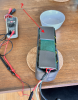
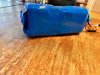
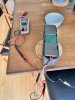
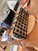
The first battery I build finally failed, so I got to make a new one!
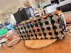
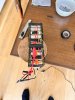
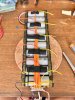
Decided to go with 21700 cells this time. Last time I posted my battery I got a lot of great feedback on mistakes I could improve.
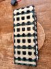
So if you feel like giving me some feedback on this build, would be very happy to hear it.
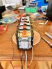
The p42a cells are from Nkon.nl
BMS is a cheap Chinese unit from ebay
The first battery I build finally failed, so I got to make a new one!
Decided to go with 21700 cells this time. Last time I posted my battery I got a lot of great feedback on mistakes I could improve.
So if you feel like giving me some feedback on this build, would be very happy to hear it.
The p42a cells are from Nkon.nl
BMS is a cheap Chinese unit from ebay
Attachments
-
 2.3 MB Views: 34
 -
 2.3 MB Views: 37
 -
 2.2 MB Views: 36
 -
 1.8 MB Views: 36
 -
 3.4 MB Views: 40
 -
 2.1 MB Views: 39
 -
 2 MB Views: 39
 -
 2.1 MB Views: 36
 -
 2.2 MB Views: 39
 -
 2.6 MB Views: 39