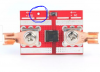
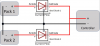
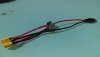
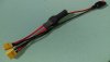
The schottky diodes I ordered were 100v 40a. I've folded the middle legs around the back of the heatsinks and screwed them together through the diode holes then soldered the discharge pos to the aluminium heatsinks which was a seperate project all in itself.
Is there a way to test this before connecting up?
Is there a way to test this before connecting up?