I mentioned a couple of weeks ago that a friend had a Woosh bike that his wife took to a local bike shop to tighten the centre stand that had come loose. They managed to fully tighten it with the motor cable trapped so that the cable was half severed, and when she tried to operate the bike, it zapped the hall sensors. I therefore had to srip it down to replace them. It's not the easiest motor to do that because the hall sensor pcb is on the side between the stator and rotors, so the motor had to be completely stripped. Here's a challenge for you technical guys. You have to shout "stop" when you reach the position in the following description when I made a disastrous error.
0. Test hall sensors to confirm faulty
1. Remove axle nuts washers and spacers.
2. Remove the two cylinder nuts that hold the motor relative to the axle.
3. Pull off the cassette spline
4. Remove the 6 side-plate screws.
5. Tap the brake side axle to lift the side-plate.
6. Wiggle off the side-plate
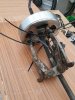
7.. pull out the motor core.
8. Remove the tiny O-ring on the laxle
9. Pull off the clutch.
10 Remove the circlip in front of the spur gear.
11. Remove the three screws that hold the spur gear.
12 Remove the spur gear.
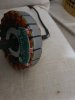
The main problem was to separate the rotor from the stator. The magnets keep them locked together and my puller couldn't latch on to anything. After thinking about it for a night, I had a solution.
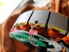
13. Fix cable ties to three spokes of the rotor and tie them to the puller legs with three more cable ties.
14. Pull rotor from stator.
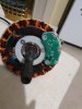
15. Remove 2 pcb screws.
16. Prise out hall sensors, which are partly retained by a thin fibreglass insulator.
17. Unsolder the three hall sensors.
18. Swap over the red insulators on the legs
19. Solder in the new hall sensors.
20. Test that the new hall sensors are switching properly.
21. Add some epoxy to retain the hall sensors in their slots.
22. Clamp and wait overnight for epoxy to cure.
23. Unclamp and insert and tighten the 2 pcb screws.
24. Reverse all the assembly steps 1 to 14
25. Test that motor works.
26. Put motor wheel back on bike.
27. Test it up and down the road.
28. Try and figure out how the weird throttle works with its secret button.
29. Realise that you made a massive mistake.
Did you stop at the right time to avoid the mistake. Answers below. I'll post some photos later when Gmail wakes up enough to upload them.
0. Test hall sensors to confirm faulty
1. Remove axle nuts washers and spacers.
2. Remove the two cylinder nuts that hold the motor relative to the axle.
3. Pull off the cassette spline
4. Remove the 6 side-plate screws.
5. Tap the brake side axle to lift the side-plate.
6. Wiggle off the side-plate
7.. pull out the motor core.
8. Remove the tiny O-ring on the laxle
9. Pull off the clutch.
10 Remove the circlip in front of the spur gear.
11. Remove the three screws that hold the spur gear.
12 Remove the spur gear.
The main problem was to separate the rotor from the stator. The magnets keep them locked together and my puller couldn't latch on to anything. After thinking about it for a night, I had a solution.
13. Fix cable ties to three spokes of the rotor and tie them to the puller legs with three more cable ties.
14. Pull rotor from stator.
15. Remove 2 pcb screws.
16. Prise out hall sensors, which are partly retained by a thin fibreglass insulator.
17. Unsolder the three hall sensors.
18. Swap over the red insulators on the legs
19. Solder in the new hall sensors.
20. Test that the new hall sensors are switching properly.
21. Add some epoxy to retain the hall sensors in their slots.
22. Clamp and wait overnight for epoxy to cure.
23. Unclamp and insert and tighten the 2 pcb screws.
24. Reverse all the assembly steps 1 to 14
25. Test that motor works.
26. Put motor wheel back on bike.
27. Test it up and down the road.
28. Try and figure out how the weird throttle works with its secret button.
29. Realise that you made a massive mistake.
Did you stop at the right time to avoid the mistake. Answers below. I'll post some photos later when Gmail wakes up enough to upload them.