

I have a Fun 2 Ride scooter 36v 10ah lithium battery I would like to increase the torque. Can anyone recommend an Unrestricted after market controller or do they all come restricted ? Thanks
Speed controller fun2ride ped
- Thread starter robert1976
- Start date
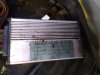
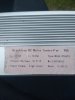
Here it is CheersNo. show us what it looks like, then I'll give you indtructions.
An easy one to add a bit more current or torque to.
I will leave it to vfr to discuss as he has been the one person involved, I try not to steal someone else's thunder.
I will leave it to vfr to discuss as he has been the one person involved, I try not to steal someone else's thunder.
That's an easy one to adjust.
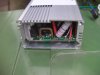
That shunt (staple-like thing) is a resistor. The CPU in the controller measures the voltage on either side of it. When current flows through it, the voltage drops on one side in proportion to the current, so the CPU knows how much current is flowing and uses that to impose its limit of 15 amps.
The plan is to change the shunt's resistance to get less voltage drop, so the CPU thinks less current is flowing and allows more.
The controller and battery can normally handle something like 30% more current, so we want to bring it closer to that limit.
You do it by adding solder to the shunt. Solder (if thick enough) has zero resistance, so when you put solder on the shunt it's resistance goes down in proportion to its unsoldered length.
As a starting point, you should try about 20%. You have to measure or estimate the length of the unsoldered shunt as it is now, then estimate or measure where 20% comes to. you don't need to be exact. Then add solder to it to cover that 20%. Use plenty of heat. make sure that you only get solder on the shunt and watch out that it doesn't go through the hole that the leg is in and make a massive blob on the other side.
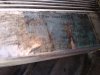
It should end up looking something like this. Ideally, it should be a bit thicker, and that one is about 33%, which was OK because the current was set very low in the first place. In your case, start with the solder just up to the start of the bend on either leg. the limit would be around where the bend finishes at the top. If 20% isn't enough oomph for you, you can go as far as that limit. If after you've done that, your battery cuts out or the controller gets too hot, there are ways back, so ask again if that happens:
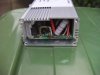
Remember, you don't get anything for nothing. Your battery will go down faster in proportion to the current. You should feel the difference in acceleration and hill-climbing, but it won't change the motor's maximum speed, though it will help you to hold a higher speed. Try not to let the motor run with full power for too long when it gets bogged down at low speed. It's high power at low speed that overheats and damages things.
That shunt (staple-like thing) is a resistor. The CPU in the controller measures the voltage on either side of it. When current flows through it, the voltage drops on one side in proportion to the current, so the CPU knows how much current is flowing and uses that to impose its limit of 15 amps.
The plan is to change the shunt's resistance to get less voltage drop, so the CPU thinks less current is flowing and allows more.
The controller and battery can normally handle something like 30% more current, so we want to bring it closer to that limit.
You do it by adding solder to the shunt. Solder (if thick enough) has zero resistance, so when you put solder on the shunt it's resistance goes down in proportion to its unsoldered length.
As a starting point, you should try about 20%. You have to measure or estimate the length of the unsoldered shunt as it is now, then estimate or measure where 20% comes to. you don't need to be exact. Then add solder to it to cover that 20%. Use plenty of heat. make sure that you only get solder on the shunt and watch out that it doesn't go through the hole that the leg is in and make a massive blob on the other side.
It should end up looking something like this. Ideally, it should be a bit thicker, and that one is about 33%, which was OK because the current was set very low in the first place. In your case, start with the solder just up to the start of the bend on either leg. the limit would be around where the bend finishes at the top. If 20% isn't enough oomph for you, you can go as far as that limit. If after you've done that, your battery cuts out or the controller gets too hot, there are ways back, so ask again if that happens:
Remember, you don't get anything for nothing. Your battery will go down faster in proportion to the current. You should feel the difference in acceleration and hill-climbing, but it won't change the motor's maximum speed, though it will help you to hold a higher speed. Try not to let the motor run with full power for too long when it gets bogged down at low speed. It's high power at low speed that overheats and damages things.
Last edited:
Don't suppose anyone can lead me to wireing diagram please.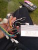
That's awesome thanks. Will have to let you know how goes. I've still got to get s batteryThat's an easy one to adjust.
That shunt (staple-like thing) is a resistor. The CPU in the controller measures the voltage on either side of it. When current flows through it, the voltage drops on one side in proportion to the current, so the CPU knows how much current is flowing and uses that to impose its limit of 15 amps.
The plan is to change the shunt's resistance to get less voltage drop, so the CPU thinks less current is flowing and allows more.
The controller and battery can normally handle something like 30% more current, so we want to bring it closer to that limit.
You do it by adding solder to the shunt. Solder (if thick enough) has zero resistance, so when you put solder on the shunt it's resistance goes down in proportion to its unsoldered length.
As a starting point, you should try about 20%. You have to measure or estimate the length of the unsoldered shunt as it is now, then estimate or measure where 20% comes to. you don't need to be exact. Then add solder to it to cover that 20%. Use plenty of heat. make sure that you only get solder on the shunt and watch out that it doesn't go through the hole that the leg is in and make a massive blob on the other side.
It should end up looking something like this. Ideally, it should be a bit thicker, and that one is about 33%, which was OK because the current was set very low in the first place. In your case, start with the solder just up to the start of the bend on either leg. the limit would be around where the bend finishes at the top. If 20% isn't enough oomph for you, you can go as far as that limit. If after you've done that, your battery cuts out or the controller gets too hot, there are ways back, so ask again if that happens:
View attachment 42244
Remember, you don't get anything for nothing. Your battery will go down faster in proportion to the current. You should feel the difference in acceleration and hill-climbing, but it won't change the motor's maximum speed, though it will help you to hold a higher speed. Try not to let the motor run with full power for too long when it gets bogged down at low speed. It's high power at low speed that overheats and damages things.
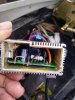
From bottom right clockwise;
Probably ignition switch on/off
Can't see where the green goes.If three pins, then three speed switch. if 2 pins, brake switch.
Throttle
Motor phase wires
Orange probably battery voltage for charge indicator
Battery
Pedal sensor
Blue probably high level brake (not used)
Green and yellow don't know
Orange possibly motor direction, otherwise might be ignition
White probably speed limit
Motor hall sensors
I don't see a connector for the brake switches, which is unusual. do you have brake switches?
Cheers. Yeah the orange one weird. I think the whit is speed limiter think 12mph if plugged in and 15.5 unplugged. Till I sort battery not shore.From bottom right clockwise;
Probably ignition switch on/off
Can't see where the green goes.If three pins, then three speed switch. if 2 pins, brake switch.
Throttle
Motor phase wires
Orange probably battery voltage for charge indicator
Battery
Pedal sensor
Blue probably high level brake (not used)
Green and yellow don't know
Orange possibly motor direction, otherwise might be ignition
White probably speed limit
Motor hall sensors
I don't see a connector for the brake switches, which is unusual. do you have brake switches?
It's got alarm and immobilizer on it.
Cheers for input
