Swapping KT-LCD1 to LCD5 (with different plugs)

Wheel-E

Pedelecer
Jul 14, 2017
97
27
Brighton
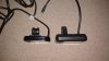
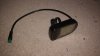
Me again! I need some advice and possibly reassurance before I dive in. I'm currently running a Cyclotricity kit with Julet connectors on everything and I've just received an LCD5 from BMS with the more usual white connector. My plan is swap the current LCD1, to have a smaller and more capable display in the LCD5.

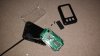
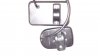
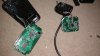
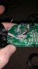
I'm hoping to keep everything as tidy as possible and keep the loom running through the frame. Is it feasible for me to open both displays and desolder the old cable and solderinto the new display? Do you think it will be obvious? I'm hoping that the wires will be the same colour even though they're different connectors.

Has anyone tried similar? It's the only way I can imagine keeping everything tidy.
 
D

Deleted member 4366

Guest
Just cut the connector off and solder the wires together. Put some heat-shrink over the individual wires and some thicker over the total. I do it all the time. It only takes a few minutes.
 

anotherkiwi

Esteemed Pedelecer
Jan 26, 2015
7,845
5,785
The European Union
<Thread hijack alert>

I asked this question, which went unanswered, elsewhere:

How many wires are there between the KT buttons and the LCD? I want to use a Higo plug rather than solder the wires.

Ta!
 

Wheel-E

Pedelecer
Jul 14, 2017
97
27
Brighton
Thanks @d8veh. Your guidance and reassurance gives me the courage to attempt these things and move closer to my dream bike.. In the end I compromised and soldered the wires inside the LCD5. I could have soldered directly to the board but it was late, I didn't want to risk lifting any tracks and the way things turned out I can resplice the LCD1 or LCD5 onto different connectors if I need to. Having swapped my Cylotricity Stealth to a new frame, I'm trying to keep everything as clean as possible with cables routed inside the frame.

Look how much smaller the LCD5 is:

IMG_20171218_224714138.jpg

Opened up the LCD1. Gently wedge open the outer case. The whole thing is well waterproofed with a clear plastic inner case around the display. The white bits in each corner are hiding screws. Dig through that with a screwdriver to find the screws and release:

IMG_20171218_230737005.jpg

The LCD5 is a bit easier, and has three screws holding it together:

IMG_20171218_225109012.jpg


Five wires in each display. All the same colours:

IMG_20171218_231013908.jpg

Sealing wires with heatshrink after soldering:

IMG_20171218_235457435.jpg

Finished product with Julet connector:

IMG_20171219_240058980.jpg

I did this all late last night. It's installed on the bike and the throttle works but not speed. Today is the day I get to do some testing and get all the settings dialled in. The LCD1 I was using was had access to less prameters than the LCD5 maybe as it was a custom Cyclotricity version - not sure.
I'm hoping that Cruise will become available, but I'm happier with the smaller size, the display of voltage and being able to adjust the screen brightness.
 
Last edited:

Wheel-E

Pedelecer
Jul 14, 2017
97
27
Brighton
<Thread hijack alert>

I asked this question, which went unanswered, elsewhere:

How many wires are there between the KT buttons and the LCD? I want to use a Higo plug rather than solder the wires.

Ta!
5 wires. Same colours in each display. Where are you getting the Higo plugs from?
 

anotherkiwi

Esteemed Pedelecer
Jan 26, 2015
7,845
5,785
The European Union
  • Informative
Reactions: Wheel-E

Wheel-E

Pedelecer
Jul 14, 2017
97
27
Brighton

anotherkiwi

Esteemed Pedelecer
Jan 26, 2015
7,845
5,785
The European Union
Are you sure we are talking about the same thing? I need to cut the wire between the external buttons of a KT LCD-3 and reconnect with Higo plugs. That cable looks mighty thin for 5 wires.

The reason? I want to put the LCD up front between my feet where I can see it and the buttons on the trike handlebar :) I want to order the Higo plugs before cutting and splicing in the extension so as to be off the road for the shortest time possible.
 

Wheel-E

Pedelecer
Jul 14, 2017
97
27
Brighton
Are you sure we are talking about the same thing? I need to cut the wire between the external buttons of a KT LCD-3 and reconnect with Higo plugs. That cable looks mighty thin for 5 wires.

The reason? I want to put the LCD up front between my feet where I can see it and the buttons on the trike handlebar :) I want to order the Higo plugs before cutting and splicing in the extension so as to be off the road for the shortest time possible.
Aaah! Sorry Kiwi I misunderstood. None of the LCDs I've used have external buttons so I can't be sure. I would imagine it wouldn't be more than 4 wires and maybe only 3. In your shoes I'd buy plugs with 4 connectors giving you a spare if needed.

I've just had a look inside the LCD1 (with integrated buttons) and can see that the three buttons have a common ground and one circuit board track each. I reckon your LCD3 external buttons might be the same four connections. Why not gently crack open your buttons and take a look?
 
  • Like
Reactions: anotherkiwi
D

Deleted member 4366

Guest
Are you sure we are talking about the same thing? I need to cut the wire between the external buttons of a KT LCD-3 and reconnect with Higo plugs. That cable looks mighty thin for 5 wires.

The reason? I want to put the LCD up front between my feet where I can see it and the buttons on the trike handlebar :) I want to order the Higo plugs before cutting and splicing in the extension so as to be off the road for the shortest time possible.
There are no connectors between the buttons and the LCD. They're hard wired. There's nothing to stop you adding connectors, but I'd rather just extend the wire by soldering in an extension piece, which would be more reliable than connectors.
 

anotherkiwi

Esteemed Pedelecer
Jan 26, 2015
7,845
5,785
The European Union
There are no connectors between the buttons and the LCD. They're hard wired. There's nothing to stop you adding connectors, but I'd rather just extend the wire by soldering in an extension piece, which would be more reliable than connectors.
I want to be able to remove the LCD easily and place it in another location, for that I want different length extensions. You really don't want bundles of excess wire on a trike, there is enough long cable runs as it is :)
 

Wheel-E

Pedelecer
Jul 14, 2017
97
27
Brighton
I want to be able to remove the LCD easily and place it in another location, for that I want different length extensions. You really don't want bundles of excess wire on a trike, there is enough long cable runs as it is :)
How about gently opening the display and taking a peek. It looks like it's just screws with the LCD3. Pry open gently remembering that where both cables enter the display will be sealed with silicon. Should be easy to see how many wires are coming in, then you can put it back together and continue using until you have the connectors and make the modifcations.

You have the option of splicing the cable internally as I have done or externally as D8veh suggests. Same for your buttons but not sure how much room you have in there.
 

Nealh

Esteemed Pedelecer
Aug 7, 2014
20,143
8,233
60
West Sx RH
<Thread hijack alert>

I asked this question, which went unanswered, elsewhere:

How many wires are there between the KT buttons and the LCD? I want to use a Higo plug rather than solder the wires.

Ta!
My APT 80OS LCD from the defunct gsm kit has the remote 3 button handle bar function/pad, it utilises all 5 wires from the lcd to the remote pad.
I haven't opened an lcd 1 or 3 pad to look so don't know if it utilises all 5 wires but would think so, the wiring is most likely just very thin hence the overall outer wire diameter being smaller.
 
Last edited:

anotherkiwi

Esteemed Pedelecer
Jan 26, 2015
7,845
5,785
The European Union
How about gently opening the display and taking a peek. It looks like it's just screws with the LCD3. Pry open gently remembering that where both cables enter the display will be sealed with silicon. Should be easy to see how many wires are coming in, then you can put it back together and continue using until you have the connectors and make the modifcations.

You have the option of splicing the cable internally as I have done or externally as D8veh suggests. Same for your buttons but not sure how much room you have in there.
Both of mine are potted... :(
 

Wheel-E

Pedelecer
Jul 14, 2017
97
27
Brighton
Both of mine are potted... :(
Looks like you'll need to go with d8veh's way then and solder your new wires to the existing. If you use a 5 pin plug you'll be alright, but potentially won't use all of the wires depending what you find when you get in there. You could always peel back the outer insulation and count the wires, then seal up with tape until you have the new connectors.
 

Wheel-E

Pedelecer
Jul 14, 2017
97
27
Brighton
I've got it up on the stand and have played around with the settings. I now have cruise control! Looking forward to going out for a spin in a bit.
 

Advertisers