
I'm in the process of building a new 14s battery pack and I've bought a Vruzend 3A 58.8V charger for this project. I was interested to see what was inside, in particular to see if it would be possible to tweak the output voltage to charge to 4.1V per cell. It cost £36.
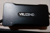
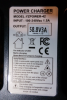
First a look at the outside. A black box with a 5.5 mm DC plug on the output and a mains cable wired directly into it. It weighs in at 432g including plug and cable. It has a fan inside, unlike many low end chargers. There seemed to be a bit of play of the output cable in the case, not in and out, but side to side as if the retaining "grommet" was too small for the hole in the case, but it was not so loose that it could be pulled out.
In terms of size comparison, here is a standard SANS 2A charger alongside it:
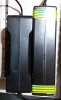
So a bit shorter, about the same width and just slightly taller.
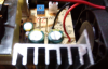
To get it open, there are two screws to remove from the base, then the other end snaps together. It looks as if there is an output voltage potentiometer, I'll have to tweak that later and check it changes the output voltage. Looks like there is a shunt for current measurement. There is a 3.15A fuse on the input side with a 400V capacitor and the main output capacitors are 63V rated.
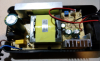
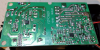
The PCB can be lifted straight out of the base, revealing a dual 358 Op amp on the output side:
Something I spotted which made me very glad I did open the case was that the solder had failed on the main input capacitor leads:
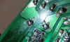
This is a common problem with lead free solder. I quickly rectified this with some decent solder and I put the charger back together and confirmed the output at 58.8V
Hopefully others will find this of interest...
First a look at the outside. A black box with a 5.5 mm DC plug on the output and a mains cable wired directly into it. It weighs in at 432g including plug and cable. It has a fan inside, unlike many low end chargers. There seemed to be a bit of play of the output cable in the case, not in and out, but side to side as if the retaining "grommet" was too small for the hole in the case, but it was not so loose that it could be pulled out.
In terms of size comparison, here is a standard SANS 2A charger alongside it:
So a bit shorter, about the same width and just slightly taller.
To get it open, there are two screws to remove from the base, then the other end snaps together. It looks as if there is an output voltage potentiometer, I'll have to tweak that later and check it changes the output voltage. Looks like there is a shunt for current measurement. There is a 3.15A fuse on the input side with a 400V capacitor and the main output capacitors are 63V rated.
The PCB can be lifted straight out of the base, revealing a dual 358 Op amp on the output side:
Something I spotted which made me very glad I did open the case was that the solder had failed on the main input capacitor leads:
This is a common problem with lead free solder. I quickly rectified this with some decent solder and I put the charger back together and confirmed the output at 58.8V
Hopefully others will find this of interest...
