CST - it's all working

D

Deleted member 4366

Guest
Getting the range right on the front derailleur can be a bit tricky. First you need to get the height right, and then rotate it round the tube until the angle to the chain is right. By rotating it a bit, you can make it reach out a bit further.

Once it's in the right position, test it with your hand to see how far it'll reach. If it still won't reach far enough, try and figure out what's stopping it . If it could reach the outer chain-ring before, it must be able to do it now because it's slightly closer. If you can reach the outer ring by pushing it by hand, then your problem is only cable adjustment.

Screw in the cable adjuster on the lever/mech as far as you can before you start. It might be a bit easier to get the start position by over-adjusting the inboard end-stop so that you have a bit more slack on the cable, i.e. set the start position slightly outboard of the inner chain-ring, so that after you clamp the cable you get a little bit of tension on it after resetting the inner end stop.

After that, it should be just a matter of setting the outboard stop and slight adjustment of the cable length adjuster.
 

103Alex1

Esteemed Pedelecer
Sep 29, 2012
2,228
67
^^ I'll have another play with it if I get time. From what you've said I think the derailleur cannot have been parallel with the front chainring like the guidance vids tell you to get it - must have been angled out from the seat tube on left as you look at it from the cranks because the extension even at full stretch when it's set parallel to the chainring isn't enough to move the chain. It's definitely an XT crankset so really cannot understand why there seems to be such difficulties problems aligning it - unless the derailleur is a SRAM or something. I can't easily tell. Or maybe that's just the way they're made.

My wood inserts FINALLY turned up this morning a week after ordering them on a promised same day 1st class dispatch. Blooming useless lot !

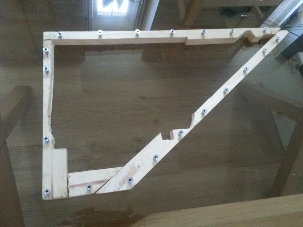
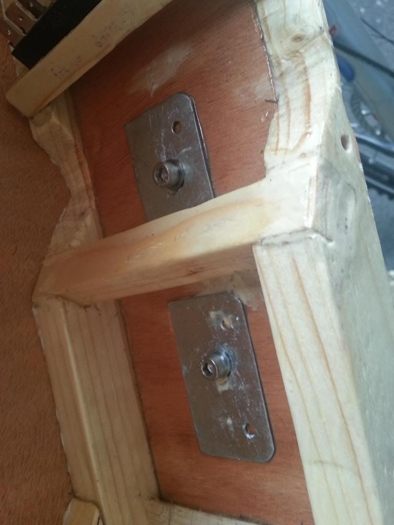
They look promising - to be inserted from the inside so screw goes through plywood side into box side and engages with insert to secure :


Only just enough by the looks of it laying them out !


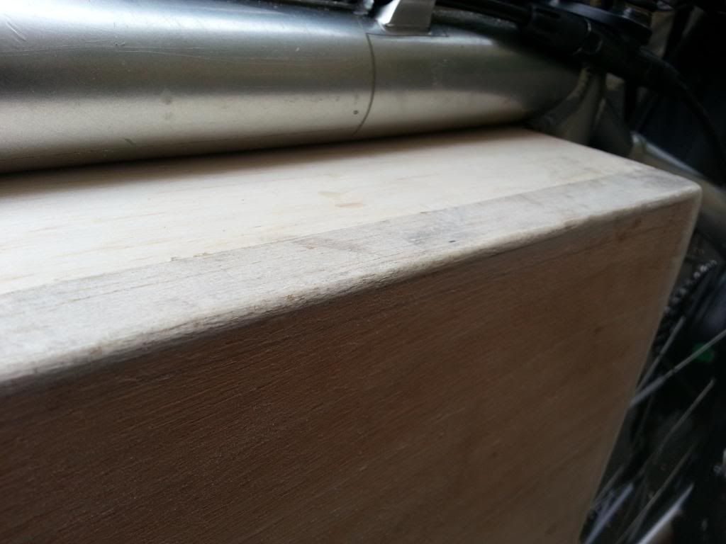
I'll get rid of the softwood at the nose and glue on balsa instead to sand /plane to shape .. it'll look better and give the 3mm plywood panel something to edge against if I cut it carefully enough. Will see how it pans out.
 
D

Deleted member 4366

Guest
I hope you drilled through the plywood outer, otherwise you'll have a hell of a job to line up the holes. If you didn't, it might be a good idea to re-position the inserts.
 

103Alex1

Esteemed Pedelecer
Sep 29, 2012
2,228
67
I hope you drilled through the plywood outer, otherwise you'll have a hell of a job to line up the holes. If you didn't, it might be a good idea to re-position the inserts.
I haven't drilled either yet. They're just laid out approximately where they'll go. Will make sure there's no more chiselling away at the sides before the inserts go in or holes drilled anyway.

Was actually intending to do it the other way around. The softwood needs pilot holes drilling first from the inside right through to the outside i.e. the face the plywood will contact - probably once frame is glued up and set final. Drill bit is the same as for an M4 bolt which will pass through the plywood side - or very slightly smaller - the gripping flanges of the inserts are marginally wider than an M4 bolt or pilot hole and therefore they should make their own grooves in the wood once all the drilling of frame and side is complete and they're knocked in.

For drilling the plywood side, it's hopefully just a case of laying the drilled softwood side on top of the inner face of the cut plywood and drilling out the 3mm holes in the plywood using an appropriate bit for M4 bolt inserted right through the pilot hole in the softwood into the plywood beneath. Even if the holes are a little small for the bolt it's not a problem as that's just a bit of reaming out with the bolt itself.

My only reservation with these inserts is their gripping power - but a bit of araldite under the head when they go in should help bond them to the wood so they don't move and add a further layer of protection against them coming loose in their positions. Finding a supporting surface it doesn't matter if I drill through into is the bigger challenge ! The holes have to line up if it's gone about this way, provided neither the plywood or the frame slip or move whilst being drilled through. Job is straightforward enough but it's all down to having the right tools as usual ! Some tests will soon tell whether I have what's needed.

Since the mushroom bolts which screw into the inserts have heads on to grip the plywood and the insert diameter is so narrow relative to the head of the bolt there is actually room for even a mm or 2 of positioning correction in the plywood. Plywood is 3mm thick versus 15mm softwood frame. The critical thing is getting the blooming pilot holes drilled dead straight and the plywood side cut right and clamped firm when holes are made in it.

I'll play about with some spare bits of wood and see what works best ! Tricky little job but it's probably as good a way as any of achieving a removeable side. I can't think of many other approaches that could work with those clearances to be honest, and as long as everything is prepped and checked before the inserts are set in the plywood side can always be remade and redrilled pretty easily. That's the theory anyway ! :rolleyes: :)
 
Last edited:

103Alex1

Esteemed Pedelecer
Sep 29, 2012
2,228
67
Best part of 2 days fiddling with bottom brackets, chainguard mounting arms, gear cables, housings and front derailleurs ... but .... the chainguard is finally fitted and the gears are working again. Hallelujah. Not to be taken on lightly !

On the plus, the whole system's had a thorough clean and grease including the crank spindles etc., new shifter cable and housing, new bottom bracket bearings/cups and a frame rethread so bottom bracket bearings screw in by hand now and only need tightening with the tool on last few threads. Works like a dream now

I frayed the 1st replacement gear cable too much trying to tighten it up as I cut it too short. That's basically what was causing the High setting not to shift the chain onto big chainring.

Bought another one today in LBS as mail order once again failed to arrive on time. Used the uncut cable length to get enough tension on it to tighten the retaining screw in place with my other hand. When it was definitely working, only then cut the gear cable and capped off with a crimp cap to stop it fraying :


Still needs some fine-tuning but it's definitely rideable again. Phew !

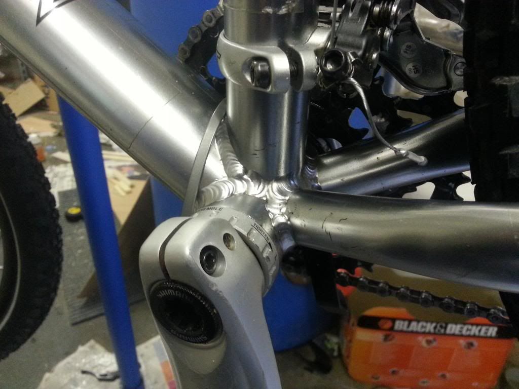
Chainguard fitting was fiddly. Basically, the bracket with top and bottom arms which the guard screws into and is fitted between external BB bearing cups and frame ends up offset on account of the front derailleur :


There's not much room for error and it helps to have your derailleur fixed first - had to remove the cranks again and readjust the bottom bracket / chainguard bracket twice when I was trying to get the front derailleur set up. The off set chainguard mounting arms angle the guard up towards the chainstay for fixing.


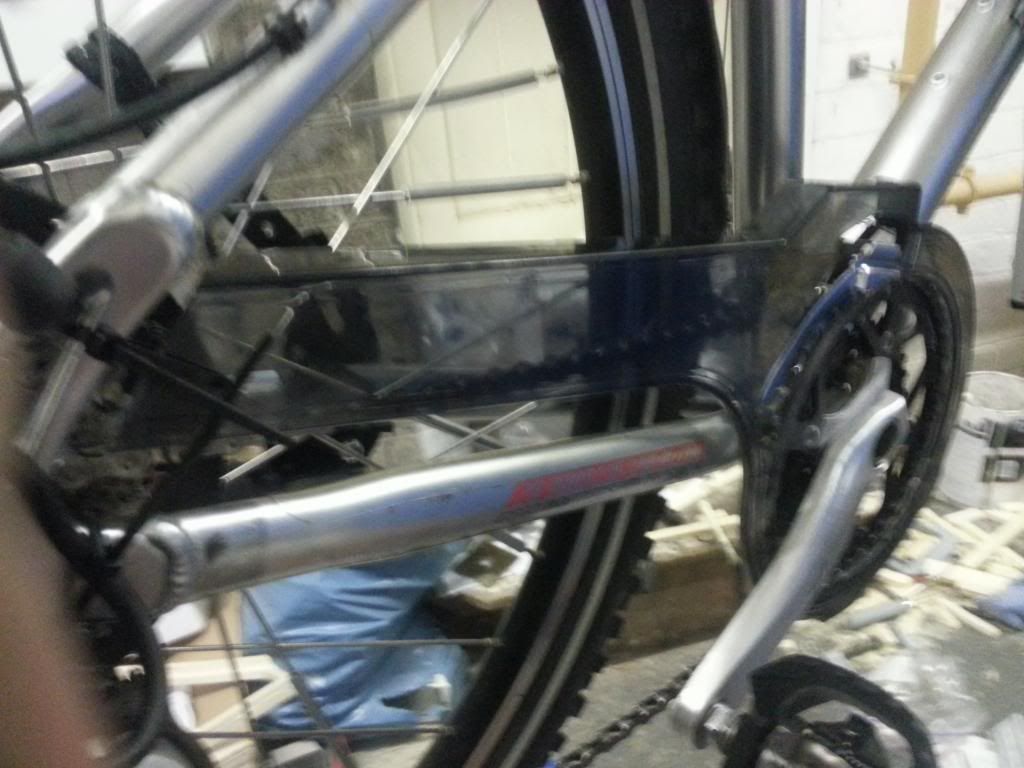
I decided to cut it down at the stay end and use a cable tie like d8veh / Saneagle. The supplied bracket wasn't very helpful. It's fine actually and very rigid.

The screws which hold the bracket to the mounting arm come supplied with blue threadlock (removeable) already in place. Saves using a locking nut.

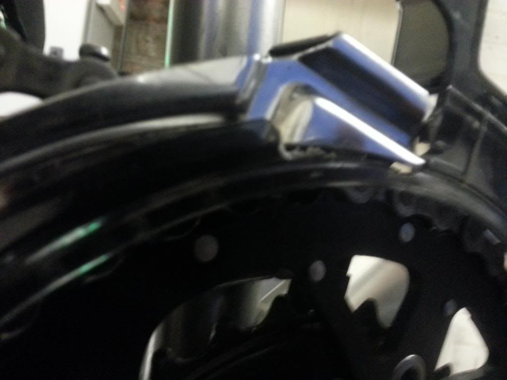
I had to make significant mods around the chainring - there's a little protruding bolt on the large chainring which was rubbing on the inner part of the lower 1/2 of the guard, so cut a few mm off the guard there with a dremel to free that. Also had to cut out significantly for the derailleur :


If I fixed the guard tighter in to the frame there would be chain rub. So you do have to mess about quite a bit - but it works and it's good value (setting the new external bottom bracket cups/bearings, £20 tool to fit & frame rethread at LBS along the way to one side !). Your options for chainguards on MTBs with derailleurs and triple front chainrings are very few and far between. None of the other ones looked at could have worked.

There will be more mods / cutouts needed to accommodate my box - but held that back till this was done so can still hopefully now make appropriate adjustments to one or the other so they work together - and can probably do it "on bike".
 
Last edited:

103Alex1

Esteemed Pedelecer
Sep 29, 2012
2,228
67
Finally managed to get a chance to play with my box a bit more. Swapped out the bolts for some longer ones .. not as neat (and take a screwdriver rather than multitool hex) but they'll do and only about £3. Nearly £8 for 20 of the other bolts of insufficient length was a bit rich - so they went back !


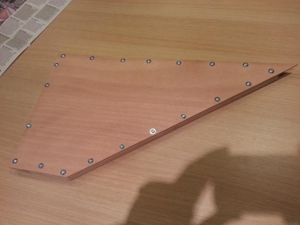
The inserts work really great - nothing else I can think of would have worked properly that close to the edge and was pretty easy to drill the holes in the plywood through the ones I'd already made in the frame. I cut the plywood side as accurately as i could but it'll get a final sand when I put the other sides on. It's easier to sand down a mm or so in places than build up.

I'm not especially happy about the position of the 2nd bolt down on the seat tube side (goes through a very thin piece of wood where frame is cut out for that huge battery) or the one in the middle of the base above the crank (the original holes through the frame were very hard to get perpendicular / accurately positioned using a deep guiding block just drilling freehand and this one was very slightly out of alignment with where I'd wanted it). May just remove bolts / inserts and fill these 2 holes in, but they do help achieve a really flush and tight join .. and by the time it's all silver you'd have to really stare at them to notice.

Hey ho ... I've now permanently set in all but these 2 inserts with 2-part Araldite to ensure inserts don't come loose. The bolts screw in effortlessly, flush and tight, so the inserts are all straight (phew !).

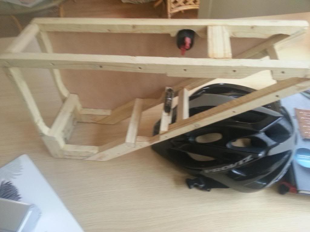
Box structure taking shape now too :


2 softwood props running between the sides are plenty strong enough to underpin the battery. I haven't glued it up yet (and need to make a few more balsa props to run between the sides / decide on position of brackets first) - but have sorted the inner main switch and charger socket support panel, and test-fitted the switches and socket :


I also need to make a decision on whether to cram in the 12V accessory charger socket. It probably will fit on the non-removeable (non-drive) side but does take up a lot of room inside that close to the nose, will need precise positioning to fit around the controller and voltage converters, wiring will need routing around it ... and it pushes the use of internal space to the limit.

My phone charger is capable of being separately hardwired to 12V supply so it's a further extra perhaps not strictly essential. More for charging electronic cigarette batteries on the move than anything else ! ..

One of those things which may end up being a step too far and not do the final looks any favours or be a final candle on a cake. Would look something like this - on a silver background .. possibly a bit further up towards the nose :


Jury's out !

So ... still a way to go - and a few more internal complications to work through ... but some progress at least.
 
Last edited:

103Alex1

Esteemed Pedelecer
Sep 29, 2012
2,228
67
Bit more progress on this - inspired by getting back in the saddle last few days !

Glued up the main frame with 2-part Araldite (great stuff - incredibly strong and sets in 20 minutes so can just hold together awkward joins) and the non-removeable side with underwater epoxy (took an age to set and after an hour and a half pressing down on it relented, used a load of books and went to bed !). It's really strong now.


The 0V 8-way Busbar sits in a slot grooved out of a softwood prop that allows a great deal of pressure to be put on it connecting and disconnecting terminals. A softwood bar at the top provides something to allow a bracket to be screwed down into. As making that involves metal I'm in complete denial... but will have to engage with it soon - leaving the top tube and down tube plywood sides off until this is made and trial fitted in case I have use wood inserts again.

Tried hard to minimize weight whilst getting enough strength and seems to be pretty good so far - less is more & all that ! It's exactly 695g at the moment including 20 screws. The extra 3 thin sides will likely take it up to about 900g empty weight. I can live with that - foam padding inside won't weigh much and I'm going to end up shortening a heck of a lot of cabling which will also likely save a lot more weight than I think. The weather-resistant rack bag I was using before weighs 1.1kg so this is actually working out a lighter solution. Really surprised at that ! The glosstex might add some grams but bottom line is this should be no heavier overall. Nice to know.

Battery is sliding in and out well (albeit tightly) - and the frame/box geometry will prevent it slipping forward. Once inside there's just about enough room for padding around it once everything else goes in.


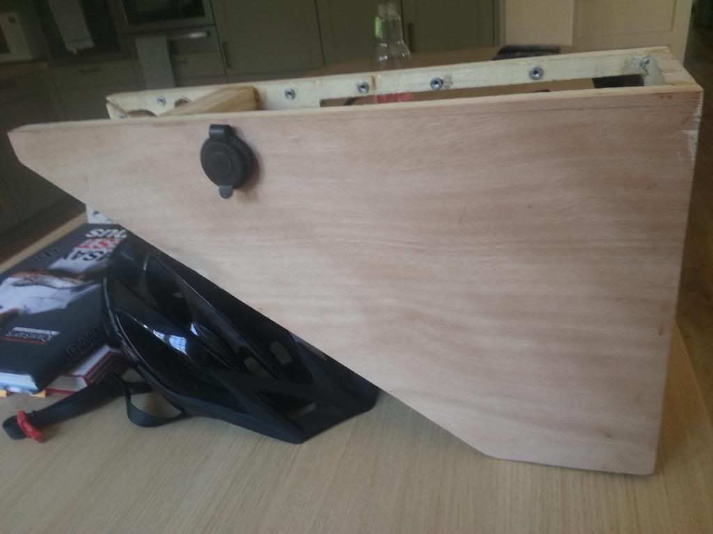
I've gone ahead with the 12V charger socket :


... and managed to dispense with the square mount since it can be screwed in tight enough flush against the side from behind not to move and has a nice rubber washer. Looks more discreet than before.

So all in all it's coming on.


Got to get to grips with the nose cone, a few more internal structural elements in balsa, remaining sides & brackets and then can move on to rewiring ... well ... pretty much everything. There's 3 voltage converters, 2 boxed switches and all the wiring and fuses to fit in there as well. Going to be a case of using all available space and just having enough clear for padding I think. One serious blooming undertaking ! Hope it all goes in.
 
D

Deleted member 4366

Guest
Saw this at the show with 2-wheel drive. I'm sure I've seen something (but better) similar before.
uploadfromtaptalk1368044073789.jpg
Sent from my GT-N7100 using Tapatalk 2
 

103Alex1

Esteemed Pedelecer
Sep 29, 2012
2,228
67
^^ was that box aluminium ?
 

103Alex1

Esteemed Pedelecer
Sep 29, 2012
2,228
67
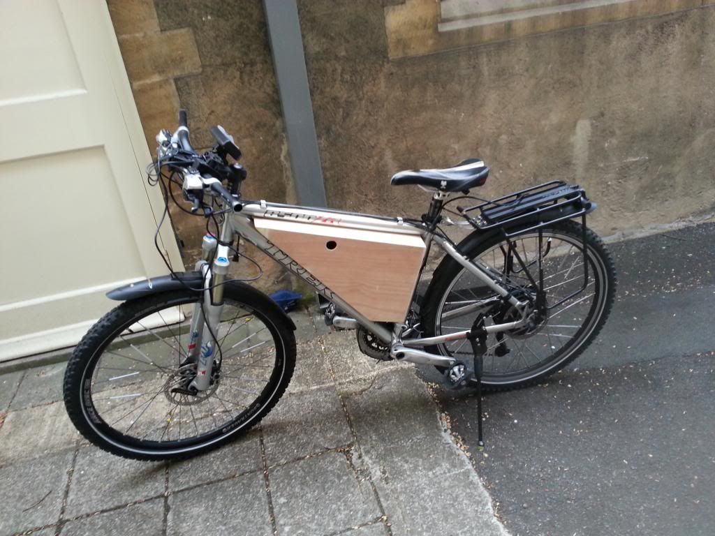
Test fit with retaining screws in place. It fits.


Just wish it didn't have to be so flipping wide :rolleyes:.

Done my best with the finishing - hate to cover up best Okoume Marine Ply ... but there's balsa joined in on the nose cone and anyhow it would only look right stained up with an old classic bike in appropriate colours.


Got minimal tooling - one hacksaw, one Tenon saw, a coping saw, a stanley knife, a Black & Decker drill and an old wooden step with a couple of G clamps - which fortunately has corners you can clamp onto. So I'm pretty chuffed with the actual construction.

Need to make a bracket to stabilize any sideways movement of the box near the handlebars. It's so accurately fitted it doesn't move without being pushed but nonetheless at speed I think it could if you went over a bump. Really hope I don't screw up the box trying to do this. I am pretty hopeless and inexperienced with metalworking and don't have any brake to make folds in it. So ... just hope I don't sink the ship at the last hurdle.... or ruin it cutting my teeth on using Solarfilm !
 

saneagle

Esteemed Pedelecer
Oct 10, 2010
4,356
2,142
Telford
Looks very neat. you should be able to get a pipe clamp from a plumbing shop to support the box laterally.
 

103Alex1

Esteemed Pedelecer
Sep 29, 2012
2,228
67

103Alex1

Esteemed Pedelecer
Sep 29, 2012
2,228
67
Been rewiring for hours ! Battery now has a 40A fuse before the master FET switch and Cycle Analyst shunt all wired in between switch and controller.

Also replaced the bullet connectors on controller wires and motor lead wires with Anderson Powerpoles, so both battery to controller and controller to motor now have Anderson Powerpoles.

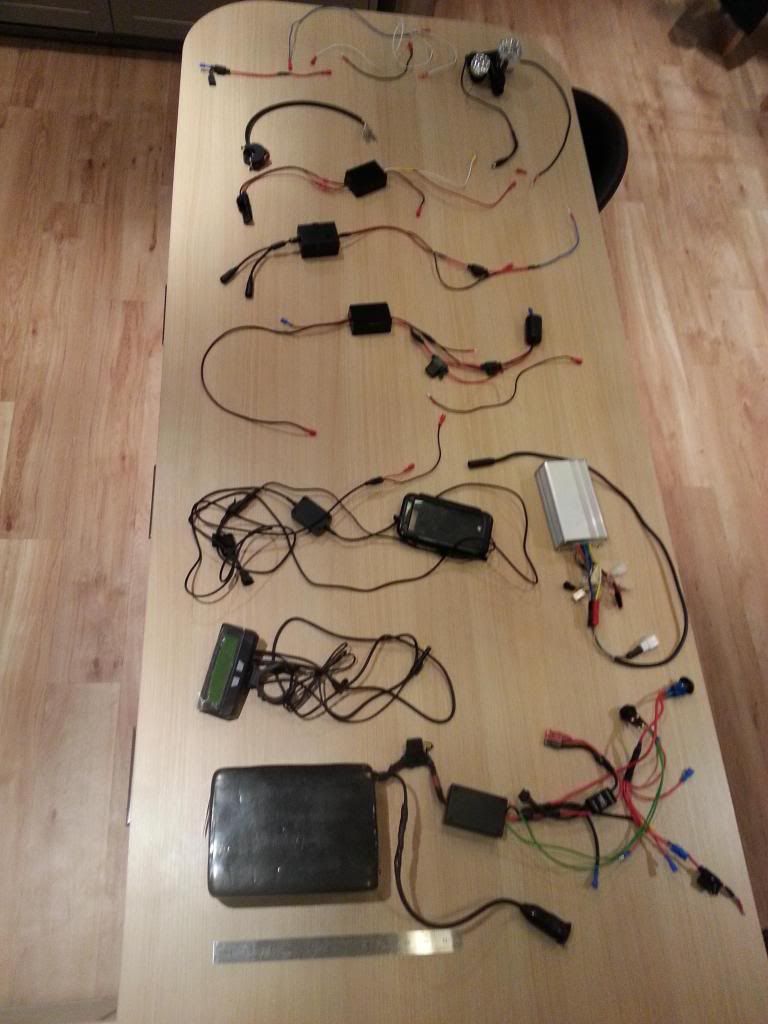
Built the final accessory circuit tonight - 12V / 3A voltage converter off secondary battery feed with a dual output to 12V charging socket on side of box and a separate hardwired proprietary mobile phone charging case for my Galaxy S3. There's an inline fuse to each but it's likely I'll only use one or the other. In an ideal world each would have its own DC-DC converter but as this is the 3rd voltage converter I've no space for any more - Have only just managed to fit this last one in with a lot of internal rejigging and designed the internal supports to accommodate it from the start.


Charging case wiring is a bit awkward to route through the box. I've basically fitted connectors before the inline fuse as the fuse can't go in / out of the box exit hole. Way too big ! Wiring therefore leads from internal fused supply out to the fully waterproofed LED switch / voltage regulator that comes with the motorbike hardwire kit. So I'm going to mount the switch box behind my seatpost under the rack arms and feed the rest of the wiring leading to integral charger connector back through the box to the handlebars / headstem. The connector should fit back through if this is the first thing to be threaded in on assembly.

I think I'm going to have to make a sequencing / assembly instruction sheet "to remind" as there's only one sequence everything will go in - and come out.

I'll have to widen the rear cable entry hole a bit. Just as well I haven't already rushed ahead and covered the box !

Anyway this is good progress now. Just got to wire up the handlebar switch to main battery supply, do the wiring for the horn and tweak the 24V / high beam lighting circuit and I should be pretty much there with this lot.

I've sanded the rough edges off every bit of wood inside the box, but still need to find a solution for some foam / padding to protect the wiring once everything is ready. If anyone has any ideas where I can easily get hold of something suitable please let me know :). I don't care how much it costs at this stage - just that it works well and I can get it reasonably quickly.
 
Last edited:

JimB

Pedelecer
Apr 1, 2013
91
0
Derbyshire
Gee whiz Alex, this looks highly impressive!

Does all this stuff require any cooling?

Jim
 

103Alex1

Esteemed Pedelecer
Sep 29, 2012
2,228
67
Gee whiz Alex, this looks highly impressive!

Does all this stuff require any cooling?

Jim
I'm hoping it'll be OK with just some decent padding round and a bit of ventilation from the cable holes. It's a trade-off against water splashing up and getting in the box. No easy answer except to leave holes open which I am a bit loath to do, but some permeable foam is probably a good compromise.

I haven't soldered any shunts and am running converters at about 30-40% of 3A capacity each max - have had them connected up for a couple of hours to see whether they get hot and so far the "over-engineering" is looking like it paid off. I need to do some more testing on anything connected to the 12V charging socket to see what amps it draws before connecting anything major in there. Will likely fit a 2A fuse after the DC-DC converter which will kill supply to anything being too hungry before it causes a heat problem at the converter.

Most of the lighting heat is generated at the lamps - all have current limiters / buck converters in them which externalise considerable heat generation from voltage reduction away from the box. Since the lights are externally mounted and have built-in heatsinks and cooling again I am hoping this is enough. The controller's the only thing I'm a bit worried about as I can't test it in situ under high load to see how hot it gets.

There don't seem to be any rule books on this stuff only vague guidelines so I'm erring on the cautious side as much as I can whilst still getting the thing built.

Finished the wiring arrays now - need to get it finished whilst I can still remember what goes where !


I honestly had no idea at the beginning that what was in my head as a bike with everything 'built-in' and fingertip / handlebar control could wind up needing quite so much work ... or so much wiring ! The overall master power switch button along with the extras isolator switch button (which shuts off supply to all the accessories if battery needs conserving) are at the back of the box behind the seat as I didn't want keys to lose, or more switches on the bars - and without an LED device that'll do this (Cycle Analyst's capabilities don't extend to this !) you have to compromise.

Swapped all but 1 mini inline fuse holder and the master 40A fuse holder for ones with an LED light on the holder that glows if a fuse blows to cut down on hunting. I could only get them with 12AWG wire attached, which was a pain as the bullet connectors that fit smaller wires from lights etc. are incompatible with that guage. So lots of splicing unfortunately. There's always something you're not planning on when stuff arrives in the post ! I've got LED fuses which glow if blown for the regular holders so no tester needed. The fuse box had to go unfortunately. Took up way too much room and no possible way to fit it in.

The handlebar light/horn switch actually cut down on the primary accessory tap wiring loom needs as it acts as a single input multiple output feed. I either hadn't chosen the switch when I got the loom or didn't understand how it worked at that time, so I have 3 spare battery tap supply wires if anything else can possibly be found space for at a later date, that can just be plugged into. I'll just cap them off with a Lucar connector for now - definitely not disassembling that 6-way tap loom ! It's just the 8 0V terminal spades that are full up. I needed more 0V terminals than tap wires ... more "learning by doing" ! Have colour coded all the handlebar switch connector wires with corresponding coloured equipment wire matching the switch outputs so that will help connecting up / disconnecting. Cheated on the yellow using yellow shrinkwrap as I couldn't find any yellow equipment wire by the metre locally :eek:.

All the wood has just been treated with a double coating of "Clearcoat" - basically a resin wash like an Epoxy Wash similar to what you use when making kayaks in a way. Even though its primary use is to improve adhesion of thicker Solarfilm coverings like Glosstex and fuelproof models I chatted with the manufacturer and it has a secondary function in protection when used on wood, far better than anything you could find in a DIY store. So if after all this the box stays it should outlive the bike ... and resist latent damp and all chances of rot / mould inside and out. It needs 24 hours to dry before I can cover the box in silver Glosstex, but at a push that should be possible by the weekend now if I have time. Once I've learned how to apply the covering that is ! Getting much closer now.
 
Last edited:

103Alex1

Esteemed Pedelecer
Sep 29, 2012
2,228
67
^^ Hi and thanks. I wondered how something like that would ever fit in full rather than just as halves. The M8/M10 bolt head might be a bit severe to accommodate internally ... would have to get one and play around with it :).

In the end I couldn't get to a plumbing store in the usual "trade opening hours" so I made one from an ally roofing joist bracket I picked up in Wickes.


The bolts holding the bracket are inserted from underneath inside the box, and are 30mm machine screws. They feed up through holes in a +/- 23mm deep structural softwood support that I positioned when glueing the box up and are secured with cap nuts on the top. It's got an epoxied on rubber lining between the frame and the bracket made out of an old inner tube.

It seems to work well if not as neat as I'd hoped for (and was an absolute swine to drill straight !) - the box is now very firmly held in place with no side to side give at all.

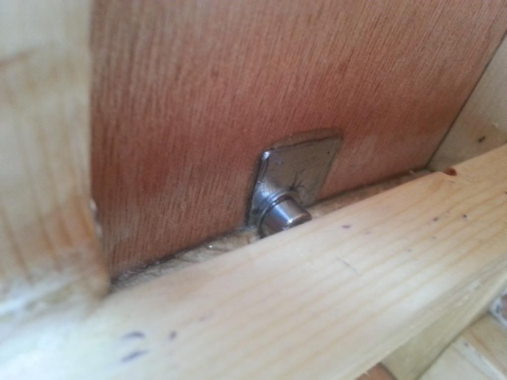
The internal bolts into the frame were also a complete nightmare to position right if I'm honest ! I didn't know about large washers a week ago and couldn't find any in B&Q for M5 bolts anyway when I did spot them in there on the shelf ! ... had already epoxied on the bits I dremelled off the roofing brackets to act as load spreaders at the site of the bolt holes :


This is the one along the seatpost just at the top of the switch housing panel, cut with a hacksaw (far quicker than the dremel tool !) then ground down to fit and epoxied on. By a miracle of luck it's just below the battery support and I can also still get the bolt screwed in and out with a regular hex minitool :


The frame has moulded washers round the bottle holes - they're a mixed blessing as they get in the way of sliding the box in and out. But I carefully sanded out grooves in the bottom and side to allow for them and they're hidden by the side panel when it's fixed on. The fixings really need to be thought through and allowed for at an early stage as it's easy to wind up boxing yourself into a corner or obstructing some of what's in the box with bolt heads etc. if you're not very careful about positioning stuff around them.
 
Last edited:

103Alex1

Esteemed Pedelecer
Sep 29, 2012
2,228
67
Well I almost got it out for a test ride with battery & controller rigged up in the box tonight. Have to admit I was a bit apprehensive as it's been off the road so long and the last time I actually rode it in its previous incarnation several weeks ago I ended up with the bike over on the pavement and me on a stretcher lol.

Anyhoo .... it's got to be done. Stupidly procrastinating about having to clamp the (now heavy) bike by its carbon seatpost on my stand (nowhere else to clamp now !) I checked and rechecked everything was tight and was just about to set off.

A couple of weeks ago or thereabouts I swapped the wires on my double throttle cruise control to reverse directionality of the 3-sp switch but haven't had the bike connected up since doing that. 2 surprises. The switch was STILL the wrong way round. Really don't know how that's happened. So when I selected what should have been normal throttle the bike tried to take off.

I always hold the rear brake when setting off so was able to overpower the motor till I switched off the cruise, but it was a bit nerve-racking that the brake switch didn't cut in.

So test ride abandoned, bike up on the stand and basically the problem seems to be the plastic connector between controller and switch isn't working reliably. It was under slight tension and the pins were not sustaining contact. Plus the connector breaks loose far too easily. It worked when I straightened the pins and held the connector together.

I think it may have to be replaced with something more reliable, but finding decent connectors for thin wires is a real pain. I haven't found any small wire connectors I really think are up to much yet that can be got hold of in a day or two. Don't want to take any more chances with that bike... even if there have been a few too many ha'pennies and way too much tar under the bridge already !

Still completely perplexed about the throttle switch. Will have to have that apart again and see what I've done (!)
 
Last edited:

103Alex1

Esteemed Pedelecer
Sep 29, 2012
2,228
67
Spent ages taking apart the throttle and swapped the wires, put it all together again. Now the 3sp switch housing has cracked in half when putting it back on the handlebars. Must have overtightened it.

I am completely sick of all this. As soon as I get one thing sorted another problem arises. Been going on for months and months and I've only been able to ride the bike a few times.

False economy. If I'd bought a ready-made bike I could have been riding it for the last few months, living the life it was all meant to facilitate and have something with a ready resale market afterwards. Saved myself weeks of work too. If only there was one available that would give me the spec I needed. Definitely a desperate last ditch saloon option for if you really don't have the funds to buy a new bike. How I am even still going with this bike build beats me - it's like a never ending nightmare.

I'm pretty much convinced the conversion route ain't for me. This is a one-off and I won't be doing it again. So now I have no throttle mechanism and need a 3sp switch from somewhere to remake the whole f****** array again. What a waste of time.
 

Advertisers