Decyphering Power controller wiring

mzsupa5

Finding my (electric) wheels
Feb 27, 2024
7
1
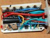
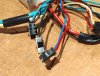
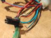
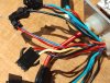
I volunteer at a charity that refurbishes bicycles and recently rescued some bits from a stolen/recovered 20" wheel folder with a view to converting a previously rescued Dahon folder. Unfortunately because a lot of the wiring was inside the frame and had to be drawn out through small holes I wasn't able to record what connected where. Other bits had plugs missing and twisted wire connections. So what I have is a Bafang 8Fun rear wheel with 3 pin connector. Minimalist handlebar controller with On button, 3 assist levels, battery monitor and light switch. Twist throttle, and one brake, motor cutout switch. I will need to get a pedal crank sensor and wheel speed sensor in due course but want to establish that the motor runs before getting in too deep so first thing is to get it to run on the throttle, which has 3 wires, red white and black.

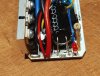
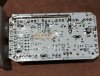
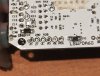
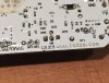
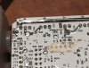
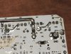
I have opened up the control box, a CE G3M20211-1592-16 to trace continuity from the various plugs to points on the PCB. Most of the red wires connect to a point mrke 5v, so presumably the 5 volt supplies apart from one that is connected to the point where the red 36v supply from the battery is connected. All the blacks connect to various grounds. There are two points BK1 and BK2 which I am guessing are the brake motor cutouts.

The battery input wires and three motor wires are obvious.

This leaves some mystery wires.

The red that connects to 36v is paired with a blue that connects to a PCB point marked MS

A set of three, Red 5v, Black to ground. Green to HV (or HU?)

A set of three, Red 5v, Black to ground.Yellow to VP (or UP?)

A pair, Black ground, Green to POR.

Does anyone know what MS HV VP and POR stand for?

Thanks for reading , If you got this far :)

Tony
 

thelarkbox

Esteemed Pedelecer
Aug 23, 2023
690
219
oxon
Google for 'ebike sensorless controller pinout'
beyond the connections common to most ebikes, you may also have light power and a key control switch both of which may only have 2 wires ..
even if present its not advisable to use a controller fed power source for lights as the internal transistor isnt very capable and can easily be overloaded by 3rd party lighting additions.

some bikes only use 2 wires for brake sensors but still use 3 wire connectors.. ?

3 wire inputs could be brake cut off sensors a pedal assist cadence or torque sensor, a speed sensor for the wheel, or the throttle.. all basically the same type of input (bar the throttle) so a 'suk it and see' approach to testing is pretty benign as long as you get the pinout correct but with the pcb exposed confirming the 5v rail and ground should be easy enough ..

Pictures would help us help you..
 
  • Like
Reactions: mzsupa5

saneagle

Esteemed Pedelecer
Oct 10, 2010
4,175
2,069
Telford
This leaves some mystery wires.

The red that connects to 36v is paired with a blue that connects to a PCB point marked MS
They go to the control panel. The red brings the power to the switch in the control panel and the blue takes it back to provide power for the controller when switched on. Join them together to bypass the control panel. The motor should work with the throttle in that state. From the control panel, the green wire has 1v for level 1, 2v for level 2 and 3v for level 3. The motor won't activate from that. It sets the max speed for the pedal assist.

A set of three, Red 5v, Black to ground. Green to HV (or HU?)

A set of three, Red 5v, Black to ground.Yellow to VP (or UP?)

A pair, Black ground, Green to POR.
They also go to the control panel. The Black is its ground and the green is the pedal assist level, assuming the control panel is the analogue version.

Does anyone know what MS HV VP and POR stand for?


From the above, you're missing the throttle signal, the lights and the pedal sensor signal. You only mentioned yellow and green unaccounted for, so one of them should be the throttle; however, you asked about MS but didn't otherwise mention it. You can figure out which one by joining a 5v to them AFTER SWITCHING ON AND JOINING THE RED AND BLUE. Don't forget to lift the wheel when you do that.

You can test the pedal assist input by tapping it rapidly with one of the 5v wires.

You didn't mention any wire connected to MS, so I can't help you on that one. Usually anything with S in it is the throttle (speed control). If it's blue it will be the throttle, and the green would be pedal sensor.

If the control panel would be digital, it would have red 36v, black ground, green and yellow data, blue switched power for the controller, then it would need a wire coming out of the controller (often yellow) for the lights.

To summarise, you connect any live 36v wire to the blue to make the controller active, then put 5v to the throttle input, and the motor should then go. You must do it in that sequence. If the controller detects 5v on the throttle wire at the time it switches on, it won't allow power - for safety.
 
Last edited:
  • Like
Reactions: mzsupa5

mzsupa5

Finding my (electric) wheels
Feb 27, 2024
7
1
Thanks for your very helpful and comprehensive response.
Blue goes to MS so possibly throttle as you suggest.

Handlebar control has a 2x 2pin plugs, red blue and green black and 2 lose wires ,yellow and white. Light voltage is 36v I think? so easy to check.

As well as the crank sensor I am assuming that a wheel speed sensor is also needed to limit to 15.5mph?
 

saneagle

Esteemed Pedelecer
Oct 10, 2010
4,175
2,069
Telford
The blue that attaches behind the red LED is the switched power supply for the controller. In the main photo, there's another blue that loops over the capacitor. Where does that go?
 

mzsupa5

Finding my (electric) wheels
Feb 27, 2024
7
1
Had a bit of a delay getting back to this. With all your help I have managed to get everything connected so that handlebar controller powers up, motor runs on the the throttle and headlight comes on. I have no crank sensor or wheel speed sensor to connect yet but have only one 3 pin plug not connected red, black and yellow. Black is earth and when power is switched on red is 5v and yellow 4.3v. Would both crank and wheel speed sensor connect to this. (Motor is 3 pin so no internal hall sensor.)