Dud Panasonic Motor Prize

10mph

Esteemed Pedelecer
Dec 13, 2010
351
0
England
It looks like a 0.1" pitch molex type connection,
Thanks. I had not heard of Molex. My practical electronics precedes these types of connectors.
The 11 pin connector is 0.1inch pitch with rectangular cross-section pins. I may have a look in the local Maplin to see if they have this. It is only 10 pin, but might fit. I also need to pick up some LEDs. I then should be able to make rough mock up of the handlebar unit - using the information in PCB pictures from des56daw I can just about work out the necessary connections now. If I can't get a plug, I will carefully strip some insulation from the 11 wire cable harness and solder to that.
 

z0mb13e

Esteemed Pedelecer
Jul 28, 2009
578
3
Dorset
Thanks. I had not heard of Molex. My practical electronics precedes these types of connectors.
The 11 pin connector is 0.1inch pitch with rectangular cross-section pins. I may have a look in the local Maplin to see if they have this. It is only 10 pin, but might fit. I also need to pick up some LEDs. I then should be able to make rough mock up of the handlebar unit - using the information in PCB pictures from des56daw I can just about work out the necessary connections now. If I can't get a plug, I will carefully strip some insulation from the 11 wire cable harness and solder to that.
I had a quick go at tracing the layout of the handlebar PCB. I'm not sure if this is 100% accurate though...


10mph

Esteemed Pedelecer
Dec 13, 2010
351
0
England
I had a quick go at tracing the layout of the handlebar PCB. I'm not sure if this is 100% accurate though...
Yes that is what I figured out. I think the common +ve for the LEDs is either 25V or 21V. On the controller board I can see that each is probably fed from the logic circuits by a transistor and a resistor marked 302, so I calculate that would be about 7mA per LED - I will get LEDs sized for that current.

BTW very nice circuit drawing software. Is it commercial or free? I have never used circuit capture software. I always worked with pen and ink! If I ever succeed in working things out for this motor controller, I may have to come to you to make my drawings pretty!
 

z0mb13e

Esteemed Pedelecer
Jul 28, 2009
578
3
Dorset
Yes that is what I figured out. I think the common +ve for the LEDs is either 25V or 21V. On the controller board I can see that each is probably fed from the logic circuits by a transistor and a resistor marked 302, so I calculate that would be about 7mA per LED - I will get LEDs sized for that current.

BTW very nice circuit drawing software. Is it commercial or free? I have never used circuit capture software. I always worked with pen and ink! If I ever succeed in working things out for this motor controller, I may have to come to you to make my drawings pretty!
That is a free bit of software from Express PCB. They manufacture PCBs as a pool service, you submit your PCB and they etch it on one big board with loads of others and then cut them out and send them to you. Makes prototyping that much easier and affordable and saves having to order 10 pcbs when you only need 1. (In true bbc style: Other PCB pool services are available).

It's almost as cool as the 3D printing services like Shapeways and Thingiverse
 

10mph

Esteemed Pedelecer
Dec 13, 2010
351
0
England
Progress report

I have discovered a few things about the connections to the motor - I have got LEDs wired up to work as in the handlebar unit. But there is still much understand, and now I have been kicked off the kitchen table by cake making activity, so here is an update.

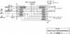
I got this in Maplins:

It is a 10 pin 0.1 Series Straight Plug PCB Header . Its rectangular pins fit exactly the 11 pin socket on the lead from the motor board. I did not even have to cut off the plastic alongside the pins. It fits neatly on the side of the 11 pin socket.

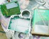
I bought some 10 way 0.1 inch matrix board with copper strips on one side (Vero strip we called it 40 years ago) so that I could solder the plug to it and then mount components, to try and mock up a handlebar unit. I have got 4 LEDs to work correctly - 2 for battery and 2 for mode I think - but I cant get the remaining two LEDs to function.

I seem to have made a mistake earlier when I reported that the power on switch was latching: ie push for ont hen on/push for off. That is not how pins 11 and 3 work now. Its just a 2 second push contact between these pins which is required for on, and the circuit, not the switch, latches in the on state. A second make should switch it off, but it does not, so I have something wrong here.

The interesting thing is that I now get the 4 LEDs giving recognisable error codes - not the no torque sensor calibration error code reported by Cyclezee, but as follows:

1. With motor/Hallsensors/torque sensor not plugged in -- 4 LEDS light for about 2 seconds then I get the following self-fault-dianosis code pattern: 2 Flashes of the 2 battery LEDs followed by one flashe of the 2 mode LEDs repeating every 3 or 4 seconds. My manual says that this means Motor Unit Error.

2. So I then plugged all the leads in to the motor, Hall sensor, and torque sensor. I now got a different pattern after the 4 LEDS came on as before on power up, then one mode light lit. Could this be the medium assist mode light? - and the unit is showing normal switch on LEDs status, albeit I am missing the battery display - on a normal working handle bar unit I should have had 3 battery LEDS to indicate full charge, since the battery was at 28.6 Volts.

The fact that I get a sequence of fault codes indicates to me that the processor is functioning - for these are surely generated in the processor.

I won't post the pin connection info for these tests, until I have made further progress and perhaps manage to sort out why I can only get 4 LEDs on, unless someone wants to see how I have connected it up.
 

z0mb13e

Esteemed Pedelecer
Jul 28, 2009
578
3
Dorset
Sounds like you are making some good progress.

Would the battery lights light up if the system is showing fault codes? Just thinking about the way some embedded systems do their diagnostics, they are usually the first set of routines to perform and if they don't complete then the execution often stops at the display fault code routine. It is possible that the battery meter is controlled by the micro controller which isn't bothering to get and display that information due to the fault...

Might be worth tracing your handle bar unit mock-up and produce a circuit diagram from that and compare it with the one from the original unit...
 

10mph

Esteemed Pedelecer
Dec 13, 2010
351
0
England
z0mb13e: Thanks. Points are noted for my next session. I want to have another go at getting some response on The 2 LEDs that don't light. I tried every sensible connection possibility which I could think of, but need to check it again.

I will have a go at a partial wiring diagram for the whole system with the limited info which I have at present. I have downloaded that Express Schematic Capture software and will try using it.

I am thinking I should get a bench power supply so I don't have to use my bike battery. I would also like to vary the supply voltage to see if I can get some response on battery voltage LEDs. Maplin do a 30V 2.5A variable supply for £90, which is a lot to spend, but it could be a helpful bit of test equipment if I do much more of this.
 

10mph

Esteemed Pedelecer
Dec 13, 2010
351
0
England
Schematic - so far

I have tried to capture what I know of the wiring in the attached schematic.

The motor and the torque sensor connections are not shown in the schematic.

I have shown where I have connected components to simulate the handlebar unit. I don't know where 2 LEDs and the mode switch should go.

I think the transistors marked TR? are connected to the circuit logic (probably to the processor) and switch the LEDs on through the 3k resistors which I can see on the board. I am not yet sure which pins two of the 6 resistors which I can see go to. They doubtless switch the remaining two LEDs.

As I have already mentioned, the power switch does not switch the power off, if I give a second press, so the connection I show to pin 3 may not be correct - all I know is pressing the switch does make power appear on the pink wire and the unit switches on with all 4 connected LEDs coming on for about 4 seconds - and is followed either by motor unit error signal, if motor is not plugged in, or just Mode2 LED illuminated, if the motor is plugged in.

I am wondering if I may have blown something by connecting pin 11 to pin 3 on the handlebar connector in order to switch the unit on. I choose this since, when I first tested the unit, I measured resistances, and pin 3 was 0.7ohms to the negative battery terminal.
 

Attachments

Last edited:

10mph

Esteemed Pedelecer
Dec 13, 2010
351
0
England
Success - PCB removed.

To get the PCB out of its housing I proceeded as follows:

The potting, I think a polyurethane, is on both sides of the board and holds it firmly in the housing. I removed most of the potting on the exposed side of the board by levering it carefully off piece by piece. It tears reasonably easily. Next I dug out the potting around the narrow gap between the board edges and the housing.

I now had to find a solvent to soften the potting under the PCB. Methyl ethyl ketone is recommended, but all I could find in my garage was some paint brush restorer, which contains the solvent light naptha aromatic. I tested this on some pieces of potting and observed that within a few minutes the polyurethane potting absorbed some of this solvent and its strength was much reduced. I could much more easily break pieces off.

I filled the gap around the PCB with this solvent and cleaned out bits of potting which appeared. Every 30 minutes or so the solvent seemed to have been absorbed so I topped it up. After about 6 hours I could move the PCB slightly with a screw driver inserted in the gap. I left it over night. This morning I got more movement, and inserted more solvent. After about 30 minutes I was able to lever the PCB out with no obvious damage. As I had hoped, the levering enabled the solvent to penetrate between the potting and the housing:


Next I will wait for the solvent to dry off and once cleaned up I should be able to find out a lot more about the board's circuitry.
 

Attachments