

D
Deleted member 4366
Guest
The problems with cheap wattmeters is that they require fairly heavy wiring, and they're not very waterproof. Luckily there's a solution that costs virtually nothing to solve those problems. You need one of this type:
http://www.ebay.co.uk/itm/Free-Ship-GT-Power-LCD-RC-130A-Battery-Watt-Meter-Power-Analyzer-Ver-2-0-/230933611688?pt=UK_ToysGames_RadioControlled_JN&hash=item35c4b744a8
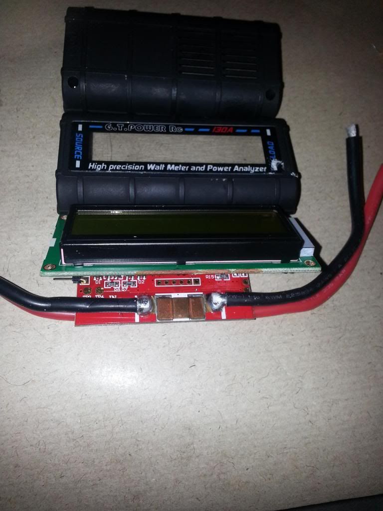
It's already fairly waterproof because it has no buttons. Everything is on the one back-lit screen; however, it has a grille underneath to let the heat from the shunt out. Wattmeters work by measuring the voltage drop over a shunt resistor. The greater the current, the greater the voltage drop. There's a CPU that takes this information and uses it to compute all the info shown in the display. We can solve both problems if we remove the shunt and place it near the battery. We then only need to send only the voltage drop information to the wattmeter. The wattmeter needs a power supply, so it needs two wires from the battery to power it, so that makes three wires if we also include the voltage drop info. the wires only need to be thin.
Here's what it looks like inside. The shunt is that coppery coloured thing at the front. All the current goes through it on the negative side. There's two PCBs. You have to bend them apart to get at the shunt:
To remove the shunt, you need a thin-bladed knife to lever it up while you use a soldering iron to melt the solder - one side at a time. It helps to transfer heat if you put a blob of solder on the iron's tip.
Here it is with the shunt removed. You also need to remove the thick red wires from the back side:
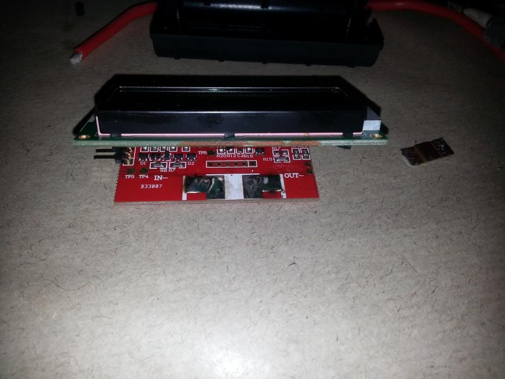
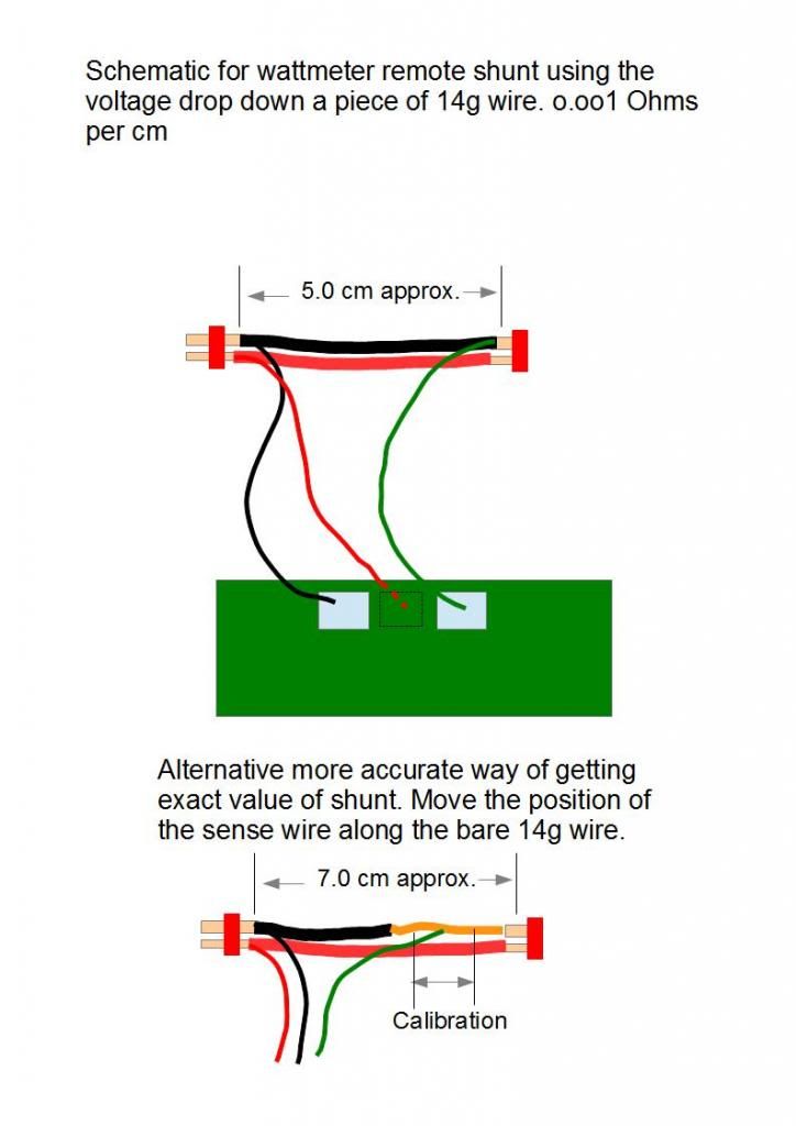
You could simply connect the battery wires and three thin wires to the shunt you removed, but I prefer to make my own out of 14g wire. 10cms = 0.010 Ohms, or 5cms = 0.005 Ohms. here's a close up of a 0,010 Ohms shunt that I made for my other wattmeter. The red and black power wires for the wattmeter go on the battery side and the white signal (voltage drop) wire on the other end of the negative wire:
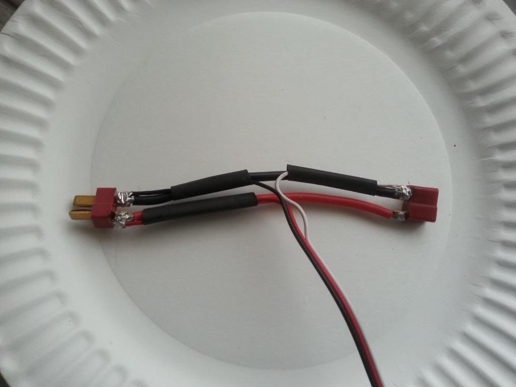
The wattmeter above requires a .005 Ohm shunt, so only 5cms long.
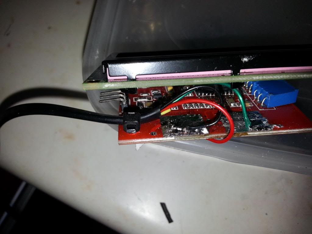
Here's a similar wattmeter that I did that shows the three thin wires soldered to the PCB where the shunrt was removed from, and the red positive on the back side where the red battery wire was before:
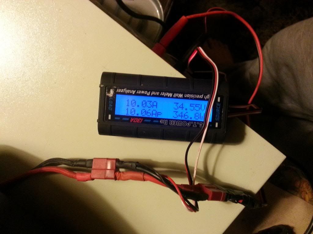
So after making the 5cm shunt and soldering the wires to the PCB, it's ready for testing. I'm lucky to have a battery tester that puts a variable programmable load on the battery, but you can check yours before and after modification by connecting it to your bike, and giving it full throttle with the brake on to slow the motor right down. this will be the max current from your controller, which is constant.
I had to adjust the length of the black wire slightly to get it exact. At 10 amps:
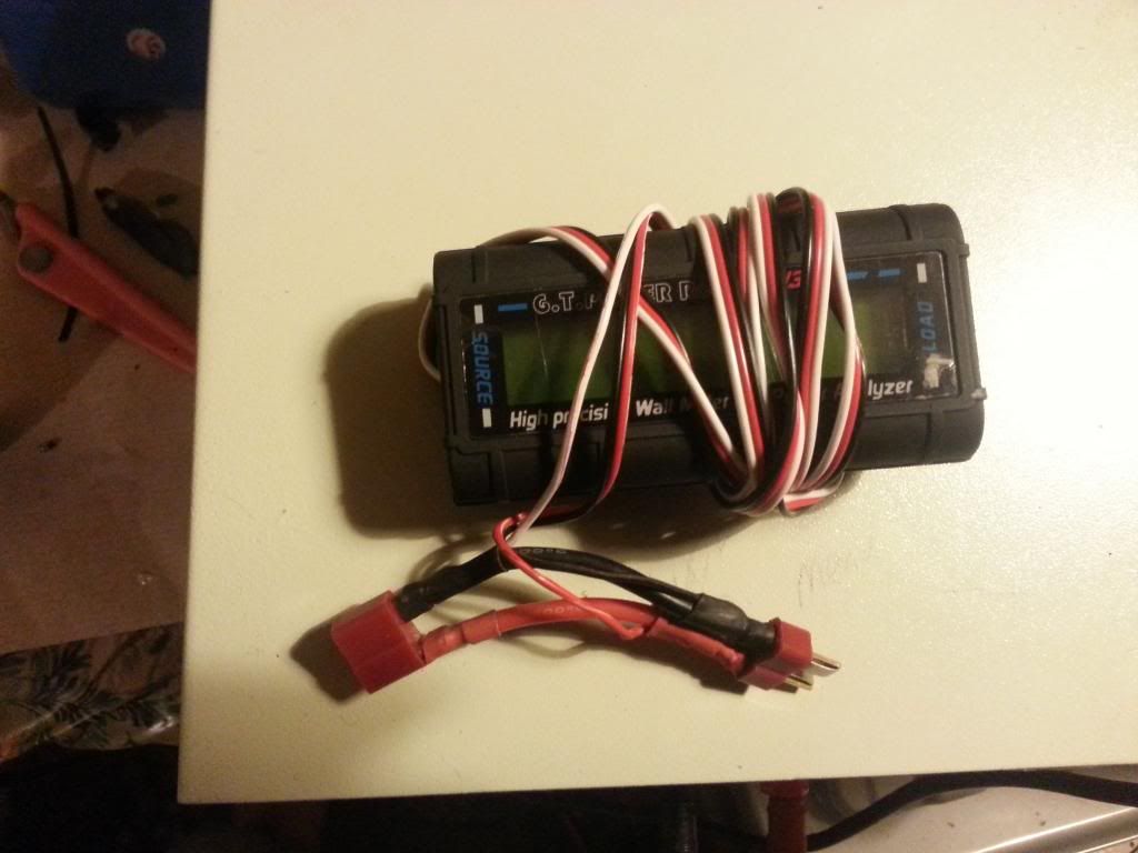
So here it is finished. Next stage is to seal it all round with silicone sealant and make a bracket to fix it to the stem before screwing it back together:
Here's the schematic:
http://www.ebay.co.uk/itm/Free-Ship-GT-Power-LCD-RC-130A-Battery-Watt-Meter-Power-Analyzer-Ver-2-0-/230933611688?pt=UK_ToysGames_RadioControlled_JN&hash=item35c4b744a8
It's already fairly waterproof because it has no buttons. Everything is on the one back-lit screen; however, it has a grille underneath to let the heat from the shunt out. Wattmeters work by measuring the voltage drop over a shunt resistor. The greater the current, the greater the voltage drop. There's a CPU that takes this information and uses it to compute all the info shown in the display. We can solve both problems if we remove the shunt and place it near the battery. We then only need to send only the voltage drop information to the wattmeter. The wattmeter needs a power supply, so it needs two wires from the battery to power it, so that makes three wires if we also include the voltage drop info. the wires only need to be thin.
Here's what it looks like inside. The shunt is that coppery coloured thing at the front. All the current goes through it on the negative side. There's two PCBs. You have to bend them apart to get at the shunt:

To remove the shunt, you need a thin-bladed knife to lever it up while you use a soldering iron to melt the solder - one side at a time. It helps to transfer heat if you put a blob of solder on the iron's tip.
Here it is with the shunt removed. You also need to remove the thick red wires from the back side:

You could simply connect the battery wires and three thin wires to the shunt you removed, but I prefer to make my own out of 14g wire. 10cms = 0.010 Ohms, or 5cms = 0.005 Ohms. here's a close up of a 0,010 Ohms shunt that I made for my other wattmeter. The red and black power wires for the wattmeter go on the battery side and the white signal (voltage drop) wire on the other end of the negative wire:

The wattmeter above requires a .005 Ohm shunt, so only 5cms long.
Here's a similar wattmeter that I did that shows the three thin wires soldered to the PCB where the shunrt was removed from, and the red positive on the back side where the red battery wire was before:

So after making the 5cm shunt and soldering the wires to the PCB, it's ready for testing. I'm lucky to have a battery tester that puts a variable programmable load on the battery, but you can check yours before and after modification by connecting it to your bike, and giving it full throttle with the brake on to slow the motor right down. this will be the max current from your controller, which is constant.
I had to adjust the length of the black wire slightly to get it exact. At 10 amps:

So here it is finished. Next stage is to seal it all round with silicone sealant and make a bracket to fix it to the stem before screwing it back together:

Here's the schematic:


