Hi,
I have completed a 10 Ah battery and, as well as my own learning, would appreciate thoughts and improvement suggestions relating to safety, performance and electrical maths.
Key points:
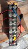
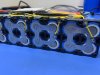
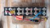
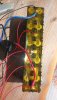
10S2P using branded 5mAh cells
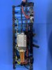
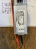
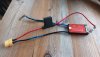
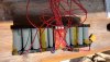
Daly 20A BMS Waterproof Common Port
30A Internal Fuse
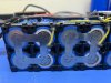
0.15mm nickel strips
17A 200W Cables
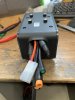
XT90 connector
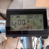
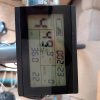
7A KT controller
BMS wiring *will need to lengthen wiring to house fuse outside heatshrink battery wrap
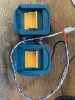
Spot welds of 0.15mm nickel using SEQURE SQ-SW2 welder *ok but could upgrade welder*
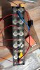
BMS soldering
Covered all points with heat resistant tape
Hot glued BMS. *Far too much length on BMS wiring. Thinking will cut to size?

Surrounded with battery insulation paper
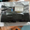
Wrapped in heatshrink and will house in LIPO bag.
* Thinking upgrade to 14A controller with XT connectors
Thank you for your time
I have completed a 10 Ah battery and, as well as my own learning, would appreciate thoughts and improvement suggestions relating to safety, performance and electrical maths.
Key points:
10S2P using branded 5mAh cells
Daly 20A BMS Waterproof Common Port
30A Internal Fuse
0.15mm nickel strips
17A 200W Cables
XT90 connector
7A KT controller
BMS wiring *will need to lengthen wiring to house fuse outside heatshrink battery wrap
Spot welds of 0.15mm nickel using SEQURE SQ-SW2 welder *ok but could upgrade welder*
BMS soldering
Covered all points with heat resistant tape
Hot glued BMS. *Far too much length on BMS wiring. Thinking will cut to size?
Surrounded with battery insulation paper
Wrapped in heatshrink and will house in LIPO bag.
* Thinking upgrade to 14A controller with XT connectors
Thank you for your time