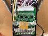
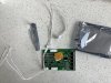
The BMS they supplied you with a 15s BMS, B3 and B5 look like they have been linked as one to be come B3 or B5 is just omitted as this will be the side for the 7 wire connector, the other side will be for the 6 wire connector so B12 I assume is not used and/or is linked to B14. By linking or omitting these two on each side of the board one then gets the 13 cell group connections instead of the 15 there would have been.
B14 on the new board is B12, the B12 new board is dead or linked so the pin isn't utilised. The last White wire next to the Red one on the old connector is B12.
There is no B0- connection so the Black thin wire on the old board can be simply solder to B- along with the thick Black wire.
The next thin White wire (old board) is B1+ so will solder to B1 wire on the new connector, the next thin wire (old board) is B2+ so connects to the other side and connector on the new board. Then alternate one at a time cut and connect each wire going odd, even, odd & even toing and froing until you get to the last thin Red wire (old board) which is B13+ will solder to B15 on the new board.
On the new board B1 is B1, B3 is B3, B5 is omitted/not used or linked to B3. Then B7 is B5, B9 is B7, B11 is B9, B13 is B11 & B15 is B13 Red thin wire.
It is a bit of a pigs ear so hopefully you can make sense of my ramblings.
The 6 wire connector is the even numbered side because there are only 6 even cell group numbers, the 7 wire being the odd numbered side because there are 13 odd numbered cell groups.
One will have to cut one wire and solder it one at a time and heat shrink the joint to the new connectors. Don't have the connectors plugged in when you solder and like wise disconnect the old connector before cutting each wire.
B5 and B12 pins on the new boards aren't used.

 3.2 MB Views: 18
 1.8 MB Views: 18