Broken battery help

crazymaster

Pedelecer
Mar 2, 2018
96
3
31
London
Hello!
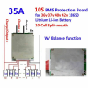
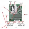
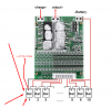
I just made a 36V 18A battery with 60 Samsung 3000mah cells and this BMS:
https://www.amazon.co.uk/gp/product/B07CMB83RN/ref=ppx_yo_dt_b_asin_title_o09_s00?ie=UTF8&psc=1

Battery worked fine, but taking longer than expected - 10-14 hours instead of 9hours with 2A charger.

BMS was hot all the time(or at least first few hours when the battery was with me, after that i gave it to my friend and i dont know)

Anyway the battery worked fine(when we dont think about this problem with longer charging)

I opened the battery and i checked all - all are the same voltage, except the first 6 batteies in front of the NEGATIVE connection.
They are showing ZERO voltage and even if i try to charge them with my 4.2V charger cor 18650cells its not reacting to them.

What may be the reason for that?
 

crazymaster

Pedelecer
Mar 2, 2018
96
3
31
London
The only one idea which i have is that maybe they are damaged because of the BMS temperature in front of them? Is that possible? Because BMS is exactly above them... but all 6 to be damaged is strange...

I tried to recharge them with connecting good cell to them paralelly but still not working... any ideas?
 

soundwave

Esteemed Pedelecer
May 23, 2015
16,188
6,319
if a 18650 is discharged to 0v the cell is toast get a better bms and replace the damaged cells as something is wrong.
 

soundwave

Esteemed Pedelecer
May 23, 2015
16,188
6,319

crazymaster

Pedelecer
Mar 2, 2018
96
3
31
London
Yes. I know Jimmy.

Anyway i found out that my BMS connector is different than the diagram on the amazon website... probably i turned it wrong side by mistake(i was had changed the first and last cable and maybe i put them wrong)

So my connector is like on this photo:
1554503342009.png

The problem is that on this photo the BMS looks the same...
Here is the link: https://www.ebay.co.uk/itm/10S-36V-35A-Li-ion-Lithium-Battery-BMS-PCB-Protection-Board-W-Balance-For-Ebike-/263934383895?_trksid=p2385738.m4383.l4275.c10

BUT the problem is that on my BMS it says CHARGE - OUTPUT - BATTERY
BUT on the photo of the ebay's one its CHARGE + OUTPUT - BATTERY
So i am confused?
 

Nealh

Esteemed Pedelecer
Aug 7, 2014
20,126
8,226
60
West Sx RH
Looking at the attachment in #4, wired up as I see it is /looks all wrong to me.
B- should be wired to 0v/ neg end of group 1 and not group 10.
B1 - B10 are all arse about face.
 
  • Like
Reactions: soundwave

crazymaster

Pedelecer
Mar 2, 2018
96
3
31
London
Looking at the attachment in #4, wired up as I see it is /looks all wrong to me.
B- should be wired to 0v/ neg end of group 1 and not group 10.
B1 - B10 are all arse about face.
So you say that they made wrong diagram for wiring?

It should be like that on the attachment here?

Anyway i made another battery with same BMS and BMS was hot again, and there is something wrong with battery... i will check tomorrow when the customer bring it to me.

"B1 - B10 are all arse about face."

I dont understand this?
 

Attachments

Nealh

Esteemed Pedelecer
Aug 7, 2014
20,126
8,226
60
West Sx RH
If the BMS gets hot then it must be wired wrong.
Show us some clear pics of your actual bms wired up and not diagrams from the seller. Also make sure we can see the connector block on the BMS so we can verify that you have wired the sense wires correctly.

B- or B0 on the JST connector should be a thin Black wire and should go to cell group #1 and soldered to the negative of the can and V reading should be 0v.
Next wire is B1+ and solders to opposite end of can (positive) for cell group #1 and V reading should be 3 - 4.2v. Next wire is for cell group #2 and V reading should be 6- 8.4v continue all connections in sequence checking voltage reading as you go to ensure correct V's are being read/seen.
When soldering sense wires never have the jst block connected until you are 100% sure the readings are all correct.
 

crazymaster

Pedelecer
Mar 2, 2018
96
3
31
London
I have connected the positive battery directly to the bike motor, and the negative goes to the BMS.

my wrong connecting is that i turned opposite way of the connector(the 10 wires with the black one at the end) - the black wire is going to B- instead of B+ So maybe that burned the battery


I will try to fix it in next hours and see if the BMS is still working or damaged
 

crazymaster

Pedelecer
Mar 2, 2018
96
3
31
London
So you try to explain me that the diagram from post 4 is wrong - i need to change the location of the black cable or just the same like "connecting it right and forgetting that its black cable on positive and red on negative side?
I mean that when we forgot the colors of the black cable all the wiring is alright?
 

Nealh

Esteemed Pedelecer
Aug 7, 2014
20,126
8,226
60
West Sx RH
Forget silly diagrams show us a pics of you battery and BMS connected.
 

Nealh

Esteemed Pedelecer
Aug 7, 2014
20,126
8,226
60
West Sx RH
I have connected the positive battery directly to the bike motor, and the negative goes to the BMS.
The thick B- goes to battery pack minus/cell group #1/0v.
The thick Red positive wire from cell group #10 should be connected to a discharge connector like a XT60 or XT90 along with thick P- from BMS, in turn this is connected to the controller ( battery Red should not go directly to the motor).

Don't know how many more times I need to say this if you want more help show us some clear pics of your BMS connected to the battery pack.
 

crazymaster

Pedelecer
Mar 2, 2018
96
3
31
London
I am replacing the damaged cell now and after that after i correct my mistake with the black wire i will post again with photo and info if it works or no :)
in 2 hours probably or less if you are still online
 

Nealh

Esteemed Pedelecer
Aug 7, 2014
20,126
8,226
60
West Sx RH
Some of us need sleep !!!
 

crazymaster

Pedelecer
Mar 2, 2018
96
3
31
London
"
B- or B0 on the JST connector should be a thin Black wire and should go to cell group #1 and soldered to the negative of the can and V reading should be 0v.
"

Now i am rewiring the bms cables(i connected them oposite to the seller diagram.

BUT from the text i quoted it looks like that the blac thin wire(bottom left from the diagram) should go to cell group 1 and soldered to the NEGATIVE side of the battery? I think that it should be to the RED according to the diagram?
 

Attachments

crazymaster

Pedelecer
Mar 2, 2018
96
3
31
London
I have connected it exactly like the diagram from manifacturer.
Charging and discharging works now. BMS is not hot.
The batteries which i replaced are 3.74V and all others are 3.77V
Should the BMS fix voltage difference now when its plugged in, or when i charge the battery?

I dont see change now, so i plugged it for charge to see whats going to happen with voltage difference
 

vfr400

Esteemed Pedelecer
Jun 12, 2011
9,822
3,986
Basildon
That diagram is completely wrong. It shows Bat 10 connected to ground. Also, the markings B+ and B- are the wrong way round for how B1 to B10 are.

I would say that what they've done wrong is mark the boxes Bat 1 to Bat 10 the wrong way round, especially because there are the optional empty pads for B11 to B13 when used for a 48V battery, and they're on the left where it says Bat 1.
 

crazymaster

Pedelecer
Mar 2, 2018
96
3
31
London
That diagram is completely wrong. It shows Bat 10 connected to ground. Also, the markings B+ and B- are the wrong way round for how B1 to B10 are.

I would say that what they've done wrong is mark the boxes Bat 1 to Bat 10 the wrong way round, especially because there are the optional empty pads for B11 to B13 when used for a 48V battery, and they're on the left where it says Bat 1.
If you say that this attachment is wrong... can you please edit it to show me how u think that it should be?
untitled (1).png
 

Advertisers