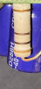
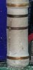
I think that large carbon resistor is part of the regulated lower voltage and 5volt circuit. One end is connected to the 48/36v and the other end goes to the voltage regulators. Its shown in the bottom of the circuit diagram I have attached below as R62 and 82ohms/3watt but this resistor number and ohms value varies with different versions of the KT controllers as far as I know.
If you google 'KT controller circuit board' and select 'images' you will see examples of this resistor with different values on different versions of the controllers as photo below.
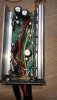
The fact that the resistor has 'blown' would lead me to suspect that there may have been a fault on the 5 volt line or that the voltage regulators may be faulty, so there is no guarantee that replacing the resistor will work. Also I suppose it would be wise to check the external wiring as a short on the 5 volt line could possibly cause this resistor to blow.
I have attached a pdf of KT controller general circuit diagram below if it helps.
 .
.
If you google 'KT controller circuit board' and select 'images' you will see examples of this resistor with different values on different versions of the controllers as photo below.
The fact that the resistor has 'blown' would lead me to suspect that there may have been a fault on the 5 volt line or that the voltage regulators may be faulty, so there is no guarantee that replacing the resistor will work. Also I suppose it would be wise to check the external wiring as a short on the 5 volt line could possibly cause this resistor to blow.
I have attached a pdf of KT controller general circuit diagram below if it helps.
.Attachments
-
600.6 KB Views: 6
Last edited: