Electrical power measurements on my Agattu

10mph

Esteemed Pedelecer
Dec 13, 2010
351
0
England
I have measured the maximum electrical power from my battery into the Panasonic Motor to be about 150 watts. This is a lot less than the bike manufacturer's rating of 250 watts.

Assuming a motor and transmission efficiency of 75% this would only provide 112 watts into the road.

I am wondering if there is something wrong with my measurements of power by means of voltage drop, because on another occasion when I have calculated watts expending in climbing a hill on I have got a much higher value:
eg A hill 40 meters high and 822metre long climbed at 14.1 mph. With a mass of 120Kg and ignoring air & tyre rolling resistance, this works out as 360 watts into the road. So, this would imply an overall 360-112= 238 watts power from my pedalling, and that is more than I thought I could provide with reasonable comfort over a climb lasting 2 minutes. I was in maximum power assist on this hill so the motor should provide twice the power of my pedalling up to the speed point where ramp down begins to occur (14 mph for the latest bikes). The calculation indicates that the motor was only providing a power equal to half my pedal power.

I can't really believe my bike is limited to around half the rated power of 250 watts, but then I can't see what is wrong with my electrical power measurements:

I took a 1kW electric fire element. This measured about 53 ohms at room temperature. By attaching to the midpoint and the two ends I could also configure it as a resistor of 13.3 ohms. A further division of the wire in a W configuration gave resistance 3.3 ohms. I attached this to the battery with and measured the voltage drop and current using two digital multimeters with the following results.


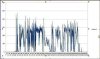
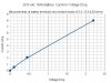
In a post at http://www.pedelecs.co.uk/forum/electric-bicycles/9317-kalkhoff-battery-connections-voltage-during-charging.html#post113288 I reported measuring a maximum drop of about 1.8 V from a no load voltage of 26.6 V. Reading of the above graph 1.8 V drop corresponds to a current of 6.6 amps which gives a power into the motor of 170 watts.

I have now done several further careful measurements of maximum voltage drop obtaining a consistent and steady values of 1.6 Volts (from 27.5V) when climbing a hill on max assist. From the graph, 1.6V corresponds to 6.0A which gives 155 watts.

Flecc has reported bursts of power of well in excess of 250 watts when climbing hills on an earlier version of the Panasonic system. I can't explain the low values which I measure. Is Kalkhoff limiting the power on my 3 speed Agattu to this low value?

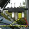
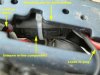
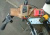
Here is my temporary arrangement with my meter taped to the equipment board on my handle bars. I am thinking of installing a small digital panel meter as a permanent indicator of battery terminal voltage.
 

Attachments

NRG

Esteemed Pedelecer
Oct 6, 2009
2,592
10
As Frank says Mike you need a Turnigy or Wattsup meter. Both use a shunt in cct to calculate current drawn. Using your DIY method you would need to measure the voltage drop across the shunt in the Panasonic motor unit to get a meaningful result not voltage drop from the battery itself.
 

10mph

Esteemed Pedelecer
Dec 13, 2010
351
0
England
...you need a Turnigy or Wattsup meter. Both use a shunt in cct to calculate current drawn. Using your DIY method you would need to measure the voltage drop across the shunt in the Panasonic motor unit to get a meaningful result not voltage drop from the battery itself.
The Watts Up has an internal current shunt. There is little room on the bike to insert the device at the crank. Even if there was room to make connections, 4 long and low-resistance leads would be required to place the display unit on the handlebars.

All I could find here on the Turnigy meter implies significant DIY modifications to operate with a remote shunt.

The expensive Cycle Analyst has a remote shunt option, I believe. I am not sure if the shunt would be small enough to accommodate in the crank area.

My method is simple. You calibrate the battery internal voltage drop by measuring voltage on the terminals against current drawn using a resistor load. Then you connect the battery to the bike and again measure voltage drop on the terminals to estimate the current being drawn by the motor. Multiply this current estimate by the battery terminal voltage and you have the power from the battery. Please explain the flaw, which I cant yet see!
 

tillson

Esteemed Pedelecer
May 29, 2008
5,253
3,197
My method is simple. You calibrate the battery internal voltage drop by measuring voltage on the terminals against current drawn using a resistor load. Then you connect the battery to the bike and again measure voltage drop on the terminals to estimate the current being drawn by the motor. Multiply this current estimate by the battery terminal voltage and you have the power from the battery. Please explain the flaw, which I cant yet see!
10MPH, I have worked through this and I can't see where the error, if there is one, creeps in. Very interesting by the way and for some reason it made me smile. This sort of experimentation reminded me of a previous life in engineering.

The only possible thing that I can think of is this:

The power output from the Panasonic motor will probably fluctuate as the input torque fluctuates due to the mechanical / lever advantage the pedal cranks have at various points about their rotation. If this is true, the current / battery voltage must also fluctuate. Is it possible that your meter is not detecting these peaks and troughs of voltage fluctuation and just giving you some sort of non-representative mean value?
 
Last edited:

10mph

Esteemed Pedelecer
Dec 13, 2010
351
0
England
The power output from the Panasonic motor will probably fluctuate as the input torque fluctuates due to the mechanical / lever advantage the pedal cranks have at various points about their rotation. If this is true, the current / battery voltage must also fluctuate. Is it possible that your meter is not detecting these peaks and troughs of voltage fluctuation and just giving you some sort of non-representative mean value?
I see fluctuations at low torque on the pedals - when I typically get fluctuation between 0.1V drop and 0.4V drop. I had thought that these fluctuations may be due to a sampling by the digital voltmeter of the variable battery terminal voltage during a pedal revolution. There are perhaps two or 3 different readings per second. I suppose my pedal cadence is somewhat less than 1 rev/second. Your suggestion could explain these observed fluctuations at low torque.

I have noticed that, as I increase the pedal torque and thus cause the motor to draw more power from the battery, the digital meter readings become steady, and I can end up with absolutely steady values at the maximum of around 1.6V drop. I think it is possible that when high power is demanded by means of the torque sensor the Panasonic control circuit averages the demand over the whole period from one pedal thrust to the next (ie at least 0.5 seconds when at about 60 rpm cadence), and demands a constant current throughout the pedal revolution. At low power demand the time constant is reduced so that the motor shuts off seemingly instantaneously when pedalling stops

Certainly, I should try another sort of meter to measure the voltage drop - perhaps an analogue one which should integrate satisfactorily over a pedal revolution.
 

NRG

Esteemed Pedelecer
Oct 6, 2009
2,592
10
Mike, going from a faded memory (Google may bring something up) a simple Thevenin model for a battery doesn't include the variable characteristics of the battery also its not possible to seperate / breakout the internal resistance from the EMF which is in series with the load. Internal resistance is variable and dependant on battery type (LI-Ion is more consistent though), SOC and temperature. Self heating effect also vary the IR.

The only accurate way to measure is with an external shunt.

The Watts Up has an internal current shunt. There is little room on the bike to insert the device at the crank. Even if there was room to make connections, 4 long and low-resistance leads would be required to place the display unit on the handlebars.

All I could find here on the Turnigy meter implies significant DIY modifications to operate with a remote shunt.

The expensive Cycle Analyst has a remote shunt option, I believe. I am not sure if the shunt would be small enough to accommodate in the crank area.

My method is simple. You calibrate the battery internal voltage drop by measuring voltage on the terminals against current drawn using a resistor load. Then you connect the battery to the bike and again measure voltage drop on the terminals to estimate the current being drawn by the motor. Multiply this current estimate by the battery terminal voltage and you have the power from the battery. Please explain the flaw, which I cant yet see!
 

10mph

Esteemed Pedelecer
Dec 13, 2010
351
0
England
The only accurate way to measure is with an external shunt.
Neal, I accept this.

However, I am just trying to get a rough idea of the discharge current. Is it the 6 Amps which I have deduced from my experiment, or 12+Amps which I would expect for a 250 watt motor on a 23-29 volt supply?

The various effects you mention are not very important in my experiment which is simply to measure the battery terminal voltage drop with the motor and then replace the motor with a resistor which gives nearly the same voltage drop and measure the current going through the resistor. (State of charge, temperature etc not changing very much in the meantime). Actually the characteristic shown in my graph of 3 points from 0.5 Amp to 8 Amp shows only a modest non-linearity: not enough to account for my low wattage result.

I have found a 100mA analogue panel meter so now I need 300 ohm 3 watt resistor. I have also found a 4 Mohm resistor which I could put in series with my digital meter, which has 10Mohm input resistance, and then I just need 1 microF capacitor to give me a 4 second time constant. I think a trip to Maplin is needed.
 

mike_j

Pedelecer
Jul 30, 2011
37
0
Firstly I apologise if the following is teaching you to suck eggs, you obviously have a strong technical background.

I think that we agree that you must make a direct measurement of current instead of using an inferential method. I suggest that a no cost option is available using a short length of your resistance wire to make a four terminal shunt. Cut a short length and connect the ends to substantial terminals, the current will flow between these. Then a little way in from each end make two more connections as voltage points for a DVM.

Now pass a known current though the main terminals, measure the voltage drop and calculate the resistance while the wire is hot. Looking at your experiment this seems a possible source of error, resistance wire has a fairly high change of resistance with temperature.

How well this works will depend to some extent on getting the shunt to a low enough resistance but it's not too critical. A 0.1 ohm resistance will only give 1.0V drop at 10 A and you can allow for this in your calculations. You should be able to make the shunt well under 0.1 ohm
 

Orraman

Pedelecer
May 4, 2008
226
1
Cleaning my Panasonic motor a few days ago I removed the terminal block and found the connection to the underside of the terminal pins appeared to be Faston connectors.

It might be possible to insert a flexible low resistance cable with male and female connectors that loops outside the plastic casing.
This would allow a current probe to send a proportionate voltage of 1mv/A to a remote multimeter.

Using this arrangement there is good correspondence between the probe reading and a meter directly connected in series when measuring similar currents for the flight motors of toy planes.

Dave
 

oigoi

Esteemed Pedelecer
Apr 14, 2011
467
7
Watt I would do (pardon the pun) in this instance is use a clamp meter that can measure dc amps to measure the current being drawn from the battery. The clamp meter would need to be put around a wire in either the positive or negative circuit coming from the battery and it would measure the current being drawn. If you know the battery voltage and the amount of amps being drawn from the battery you know the power being consumed
 

10mph

Esteemed Pedelecer
Dec 13, 2010
351
0
England
.....Now pass a known current though the main terminals, measure the voltage drop and calculate the resistance while the wire is hot. Looking at your experiment this seems a possible source of error, resistance wire has a fairly high change of resistance with temperature........
The resistance of my fire bar element did change slightly as it warmed up during my 8 Amp test, but this not a source of error since I measured the voltage drop and the current directly with meters when hot and did not need to use a value for the wire resistance.

Thanks for the tips on setting up a shunt, but I have very little space to do it in and I am not going to hack around the wiring on my nice new Agattu - still under guarantee. I suppose I could unplug the red lead below and if I had good connectors install the device you describe - it would have to be well made to be robust. Aiming for 0.03 ohm would seem sensible as it would keep the heat dissipation to 3 watt for 10 Amp flowing.

Here is the battery plug:

and here is its mounting point showing the small space available:


I have not worked out what that in-line black cylindrical component is. Any ideas?
 

Attachments

10mph

Esteemed Pedelecer
Dec 13, 2010
351
0
England
Cleaning my Panasonic motor a few days ago I removed the terminal block and found the connection to the underside of the terminal pins appeared to be Faston connectors......
Thanks for the tip about Faston connectors - I will try and buy the correct size.
 

10mph

Esteemed Pedelecer
Dec 13, 2010
351
0
England
...... use a clamp meter that can measure dc amps to measure the current being drawn from the battery. The clamp meter would need to be put around a wire in either the positive or negative circuit coming from the battery and it would measure the current being drawn. ......
There is no room to install a conventional clamp current meter of the type I have seen in shops, and then put everything back together so the bike can be ridden.

But this gives me an idea - may be they make them with a little loop that can be installed over the wire and connected to a remote display unit. If I can't buy one like this may be I could make one.
 

Orraman

Pedelecer
May 4, 2008
226
1
10mph,

Please note that my Gitane Ebike8 is now over 3 years old and the connectors do not look like those in your recent pictures.

Dave
 

flecc

Member
Oct 25, 2006
53,616
30,884
The 112 watts must be wrong in some way.

Here's the graph that member Fecn produced from his Agattu under power, showing peaks of around 400 watts and an average power of about 250 watts:

Panasonic power graph.jpg

and here's some Panasonic material on the efficiency of the new unit against the old, clearly indicating much higher wattages:

Panad.jpg
 
Last edited:

10mph

Esteemed Pedelecer
Dec 13, 2010
351
0
England
The 112 watts must be wrong in some way.
I wish I could see what causes this unexpectedly low result.

I did wonder if there could be some interaction between the PWM and phase switching in the motor unit and the sampling process in the digital multimeter. So today I set up an analogue voltmeter. I took 3 resistors in series with a measured resistance of 324 ohms, connected to one terminal of a 100mA full scale meter. This old style meter measures DC current using the magnetic field produced by a coil to deflect the pointer. It will not respond to AC, or any pulses from the PWM. I checked the calibration of the meter by noting when the DVM read 27.3V the analogue meter read 81.5mA. This actually implies a series resistance of 335 ohms, which agrees within 3% of my direct measurement of resistance and is probably within the accuracy of the various measurements.

I fitted both digital and analogue meters to the handle bars. I won't show a picture since it is an ugly lash up with parcel tape. I took the bike out on two modest slopes (perhaps nearly 5%) close to home where I could accelerate in top gear up towards 14mph where the bike starts ramping down its assistance.

As previously, the maximum steady drop on the DVM was 1.6 volts. The analogue meter dropped by between 5 or 6 mA, say 5.5mA. There are 50 divisions for 100mA so I was trying to read to less than half a division. It would have been easier to read more accurately if I had had stronger glasses on, but of course head movement due to my pedalling effort would probably then be a problem. Fortunately there was no other traffic to distract me from my readings, and the exercise was competed safely. One dog walker, doubtless noticing the mess of wires and meters, asked how fast my bike would go. I said 15 mph.

5.5mA drop with a 335 ohm series resistor corresponds to battery terminal voltage drop of 1.84 V which was about 15% more than the drop measured on the DVM.

This confirms my finding that the electrical power, which my 3 speed Agattu (2011 model) draws from the battery, is a lot less than I would expect, given that the motor is rated at 250w, and given what is shown in the measurements and graphs shown by Flecc. Perhaps this particular model from Kalkhoff has been limited in power to encourage the rider to put more effort in. I have no complaints about this low level of power the bike suits me very well indeed both at 10 mph, and also when I want a bit more exercise and try and maintain 14 or 15 mph.

However, there remains my niggling doubt about the rather large rider+motor watts I calculate for when I am climbing hills. I will have to think what more experiments I can devise to investigate this. I have a horrible feeling it could involve finding a long 5% hill which I can repeatedly ride until the battery is run down.
 

flecc

Member
Oct 25, 2006
53,616
30,884
Personally I'd trust most in the actual hill climb results and calculated power, which as you say clearly indicate the claimed wattages. Ultimately the physical performance is an undeniable factor.
 

10mph

Esteemed Pedelecer
Dec 13, 2010
351
0
England
Personally I'd trust most in the actual hill climb results and calculated power, which as you say clearly indicate the claimed wattages. Ultimately the physical performance is an undeniable factor.
Both mechanical and electrical methods have potential problems.

Hill climbing: Rider contribution hard to quantify on a Panasonic torque controlled drive; problems determining hill slope (both map contours and GPS altimetry have errors)

Electric power: Does the PWM cause problems on DC meters? Is battery drop very non-linear when PWM pulses are present?

Converting between the two we have to make assumptions about transmission and motor efficiencies.

At present I have about a factor of 2 difference between these methods, also my electrical method indicates a power much lower than expected for a Panasonic motor rated at 250 watts.

It would be nice to find a factor of two missing somewhere in the calculation of electrical power, but I can't see it. So I am now going to check for the presence pulses from the PWM reaching the battery.

I have noticed that if I stand on a pedal with the bike held stationary I can get a voltage drop of about 0.6 Volts which must correspond to about 2.5 Amps stalled current powering the motor when there is some level of thrust demand produced by activating the torque sensor. I should be able to set up a static test using a weight placed hanging from a pedal. I will then be able to investigate the waveform across the battery terminals using my main powered oscilloscope. If there are pulses from the PWM, which could conceivably upset my power measurement, they should be detectable.
 

Advertisers