GIANT TWIST Front Hub.

six9giant

Pedelecer
Apr 16, 2016
73
10
66
Maryport, Cumbria
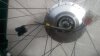
I've purchased a Giant Twist Front Hub with Hall effect.
The Wheel arrived with no details on which wire goes to which.
It has three wires (plug) for the motor and Six wires (plug) plus a outer black trailing wire for the hall effect.

I'm using this on a custom trike that I'm building whilst utilising a 1962 Pashley Trike Frame, extending the length and running with 28" Front Hub with 24" Rear wheels.

Just need help on the wires connections.
Did this hub have a built in Dynamo ?

Bryan
 
D

Deleted member 4366

Guest
IIRC, there was something unusual about the wiring apart from the colors, but I can't remenber what it was. In principle, its easy. The three thick wires are the motor power wires. the connection sequence for them can be important.
There's 5 wires needed for the hall sensors: 5v, ground and three signal wires. It's very important that you identify which is which.

The three hall signal wires work together with the three power wires. there's 26 combinations, of which three will give the correct forward movement. Other combinations can make the motor move, but with incorrect timing, which can damage the controller. You have to get the correct combination by trial and error.

Alternatively, much simpler, would be to use a sensorless controller that only has three wires to connect to those three motor power wires. In the worst case, the motor will go backwards, so you just swap any pair to make it go forward. Some motors don't work very well sensorless. you never know until you try. The KU63 or KU65 controllers are always very good at sorting out motors because they can detect and adjust themselves for the phase wire sequence and the motor phase angle. Motors can have 120deg or 60deg phase angles so normally you need the right controller.

Hopefully, someone can help you with the missing info (phase angle and hall wire identification), to make it easier.

You couldn't have picked a much worse motor for a DIY project regards wiring.
 

six9giant

Pedelecer
Apr 16, 2016
73
10
66
Maryport, Cumbria
IIRC, there was something unusual about the wiring apart from the colors, but I can't remenber what it was. In principle, its easy. The three thick wires are the motor power wires. the connection sequence for them can be important.
There's 5 wires needed for the hall sensors: 5v, ground and three signal wires. It's very important that you identify which is which.

The three hall signal wires work together with the three power wires. there's 26 combinations, of which three will give the correct forward movement. Other combinations can make the motor move, but with incorrect timing, which can damage the controller. You have to get the correct combination by trial and error.

Alternatively, much simpler, would be to use a sensorless controller that only has three wires to connect to those three motor power wires. In the worst case, the motor will go backwards, so you just swap any pair to make it go forward. Some motors don't work very well sensorless. you never know until you try. The KU63 or KU65 controllers are always very good at sorting out motors because they can detect and adjust themselves for the phase wire sequence and the motor phase angle. Motors can have 120deg or 60deg phase angles so normally you need the right controller.

Hopefully, someone can help you with the missing info (phase angle and hall wire identification), to make it easier.

You couldn't have picked a much worse motor for a DIY project regards wiring.
I got it for a song, just missing the notes.....
 
D

Deleted member 4366

Guest
If you show the wires, I might be able to figure out which is which.
 
D

Deleted member 4366

Guest
The three hall signal wires are the same colour as the three motor phase wires, so that makes the connection sequence easier. The photo is too blurred to see what the black wires are. I'm guessing that there's a temperature sensor in the motor. To find out which or the other three wires are which, you'd have to do some trial and error.

You have another problem to overcome. That motor has a special arrangement to stop the axle turning. Have you already figured out how to deal with that?
 

six9giant

Pedelecer
Apr 16, 2016
73
10
66
Maryport, Cumbria
The three hall signal wires are the same colour as the three motor phase wires, so that makes the connection sequence easier. The photo is too blurred to see what the black wires are. I'm guessing that there's a temperature sensor in the motor. To find out which or the other three wires are which, you'd have to do some trial and error.

You have another problem to overcome. That motor has a special arrangement to stop the axle turning. Have you already figured out how to deal with that?
Not yet, maybe need a few different eyes and thoughts to help me.
I thought the fork ends might slot into the two raised sections that surround the spindle
 

flecc

Member
Oct 25, 2006
52,822
30,382
In some models of the Giant e-bikes this Sanyo motor regenerated so had no freewheel. If your wheel rotates freely in one direction but is notchy in the other direction, it's a freewheeled non-regenerating version. Notchy both ways it's a regen version.

At a guess the thick black wire at the top of the connector in your photo may be something to do with the regen function for those with that feature.
.
 

Advertisers