
Morning All,
I got a bit bored last night and took apart the controller again...
I thought i'd have a go at the solder shunt modification that so may people have done on exisiting controllers to basically ramp up the amp's.
Now this really is a super easy way to modify most controllers.
The controller I have is the KU90 model from BMS battery.
This is a brushless 36v 48v sensorless controller, There pretty cheap from BMS battery so I thought if i do bugger it up i'll buy another one.
First of the controller is rated at 10amp with peaks of 20amp.
Now on the watts up meter I measure peaks of 20.4amp and peaks using lipo of around 960watt (@44v nominal)
The caps in the controller are 63v whiles the mosfets are model RU7088r MOSFETS
Specs listed on the link. So the mosfets should be good for 80v and allow some headroom on the peak amps.
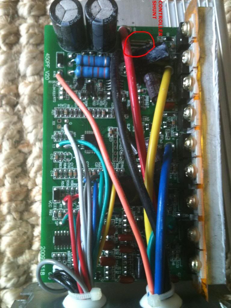
I've soldered up the legs on the shunt, effectivly decreasing the resistance.
Now there are formulars to work on the resistance you'd need to get the correct peak amps you'd like. But when soldering the legs its hard to get the right build up to what you'd like anyway.
Long story short I fired it up this morning on the bike. Twist the throttle and it works which is great...
I might have gone a bit mental on the soldering as I've now changed the peak amps from 20amp to 27.3amp.
Which is quite a considerable leap. So now pushing 1344watt peak.
Which is a good +40% increase.
Acceleration is quite a bit quicker as expected however becasue top speed is no affected my total amp hr used for the same 10.5 mile journey hasn't actually increased. I still used 3.5amp hrs even with the increase in peak amps.
Which is a little surprising as I would have thought it would have chewed up an extra amp with the extra stop starts.
Controller still stays cool and motor is still cool even though the increase in 40% torque (Which is linear to amps) should increase heat by 160%.
Looks like as long as I pedal and keep the bike speed up and not just do full on hill climbs I shouldn't see any adverse affects.
Not sure if the BPM is made for those peaks though :-(
I got a bit bored last night and took apart the controller again...
I thought i'd have a go at the solder shunt modification that so may people have done on exisiting controllers to basically ramp up the amp's.
Now this really is a super easy way to modify most controllers.
The controller I have is the KU90 model from BMS battery.
This is a brushless 36v 48v sensorless controller, There pretty cheap from BMS battery so I thought if i do bugger it up i'll buy another one.
First of the controller is rated at 10amp with peaks of 20amp.
Now on the watts up meter I measure peaks of 20.4amp and peaks using lipo of around 960watt (@44v nominal)
The caps in the controller are 63v whiles the mosfets are model RU7088r MOSFETS
Specs listed on the link. So the mosfets should be good for 80v and allow some headroom on the peak amps.
I've soldered up the legs on the shunt, effectivly decreasing the resistance.
Now there are formulars to work on the resistance you'd need to get the correct peak amps you'd like. But when soldering the legs its hard to get the right build up to what you'd like anyway.
Long story short I fired it up this morning on the bike. Twist the throttle and it works which is great...
I might have gone a bit mental on the soldering as I've now changed the peak amps from 20amp to 27.3amp.
Which is quite a considerable leap. So now pushing 1344watt peak.
Which is a good +40% increase.
Acceleration is quite a bit quicker as expected however becasue top speed is no affected my total amp hr used for the same 10.5 mile journey hasn't actually increased. I still used 3.5amp hrs even with the increase in peak amps.
Which is a little surprising as I would have thought it would have chewed up an extra amp with the extra stop starts.
Controller still stays cool and motor is still cool even though the increase in 40% torque (Which is linear to amps) should increase heat by 160%.
Looks like as long as I pedal and keep the bike speed up and not just do full on hill climbs I shouldn't see any adverse affects.
Not sure if the BPM is made for those peaks though :-(
")


