can you explain it a bit more for dummys like meThe PAS doesn't connect to the lcd s886, it is connected to the electronic controller which is the metal box with all the wiring.

can you explain it a bit more for dummys like meThe PAS doesn't connect to the lcd s886, it is connected to the electronic controller which is the metal box with all the wiring.
The PAS doesn't connect to the lcd s886, it is connected to the electronic controller which is the metal box with all the wiring.
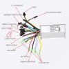
here is a video link to downloadYou have made a big mistake. You have connected one of the single green wires to a white wire that comes from the LCD. If you switch on like that, you'll kill the controller. the two single green wires are for the self-learning procedure, where the controller discovres the hall sensor and phase sequence.
The connector shown in the connection picture as 1:1 accelerator is the pedal sensor connector. You have to check that the wires on your sensor are in the same sequence, so red goes to red, black to black and whatever the other colour is to green.
The video is not very good. It keeps buffering, which makes it very difficult to follow, and each time I pause it, everything is out of focus, so I can't see what you've done. Normal still photos are much better, but you must show all the wires and connectors.
Sounds like your PAS sensor then wasn't supplied with the controller/lcd you bought so the connector is the same as the controller one, for it to work you will need the opposite male or female connector and the wiring gin the correct order to work.i cant found the right plug in the controller for the pas.... the only plug what fits it is the speed throttle conection plug but it dont work if i conect them...
here the video from wetransfer.com to download... https://we.tl/t-R7RQ0HmGA0The last video link doesn't work at all on my tablet. Use a proper hosting client like Youtube.
hmmmmm how i can know which color is positive or negative if you dont have the factory wiring plan of youtr item...Wouldn't work for me either and the first one is dodgy and my laptop went in to security alert and locked the site link.
They show the connection in a picture in their listing. It's very simple. All ebike controllers are nearly the same. The only problem is that we don't know what you've done.
Before going any further, disconnect everything except the LCD and the battery. Switch on the LCD and measure the voltage between the red and black wires on the PAS, throttle or hall sensor connector. It should be 5v.
If that's OK, connect the throttle and motor. Switch on and set the LCD to the highest level, then try the throttle.
When you've done all that, let us know what happened.
i will try it.... thank you all for helpDo what I wrote in my last post.
do i need a electronic item to measure the voltage? ore can i see the voltage on the display?Do what I wrote in my last post.