Hello all, I recently made this device and thought I'd share it with the community, both to help others and to possibly get others to help me.
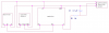
Essentially, it's an Arduino hooked up to the signal from the twist/thumb throttle, a PWM smoothing circuit which is in turn connected to the throttle signal the controller receives, and a contactless-type current sensor, like this one. It is powered by the power wire that goes to the throttle from the controller.
It works by mapping the throttle input to a target current, then modulating the throttle output signal to achieve this current. It should work with any controller that has a hall sensor throttle signal.
The smoothing circuit doesn't have to be perfect, just enough that the controller won't receive an unfiltered PWM signal, because it won't recognize that as a throttle signal. It can also never receive a straight 5 volts, or whatever the throttle power voltage is, because it will trigger a "stuck throttle" condition in the controller and cause it to shut down throttle input as a safety measure.
I will soon be implementing a proportionality to the feedback function so that it will change the throttle more drastically when it is farther from its target current. This will reduce throttle lag and increase safety, because as of right now, it takes a long time to "spool up" and "spool down" the throttle signal, essentially meaning that there is a significant delay between punching the throttle and getting to full current, or releasing it and getting to zero. This delay is on the order of a second or two. As such, I recommend that until there is such a proportionality, only those who have brake lever shutoffs use this. I do not have such sensors, and so have had a couple of instances where I was fighting the motor with my brakes while making a sudden stop. I take no responsibility for any harm or damage to you or your property or the property of others incurred by messing about with your throttle signal.
Proportionality is only a part of a Proportional-Integral-Derivative control loop, though, so if someone who has more experience with Arduino could point me in the right direction to implement the rest, I would be grateful for the extra help and smoothness of the control.
Code here. Sorry if it's over-commented, I just wanted to make sure someone who isn't familiar with Arduino can still understand what is happening.
Let me know what you think, I'd like to receive some feedback on this project that isn't just a series of numbers!
Essentially, it's an Arduino hooked up to the signal from the twist/thumb throttle, a PWM smoothing circuit which is in turn connected to the throttle signal the controller receives, and a contactless-type current sensor, like this one. It is powered by the power wire that goes to the throttle from the controller.
It works by mapping the throttle input to a target current, then modulating the throttle output signal to achieve this current. It should work with any controller that has a hall sensor throttle signal.
The smoothing circuit doesn't have to be perfect, just enough that the controller won't receive an unfiltered PWM signal, because it won't recognize that as a throttle signal. It can also never receive a straight 5 volts, or whatever the throttle power voltage is, because it will trigger a "stuck throttle" condition in the controller and cause it to shut down throttle input as a safety measure.
I will soon be implementing a proportionality to the feedback function so that it will change the throttle more drastically when it is farther from its target current. This will reduce throttle lag and increase safety, because as of right now, it takes a long time to "spool up" and "spool down" the throttle signal, essentially meaning that there is a significant delay between punching the throttle and getting to full current, or releasing it and getting to zero. This delay is on the order of a second or two. As such, I recommend that until there is such a proportionality, only those who have brake lever shutoffs use this. I do not have such sensors, and so have had a couple of instances where I was fighting the motor with my brakes while making a sudden stop. I take no responsibility for any harm or damage to you or your property or the property of others incurred by messing about with your throttle signal.
Proportionality is only a part of a Proportional-Integral-Derivative control loop, though, so if someone who has more experience with Arduino could point me in the right direction to implement the rest, I would be grateful for the extra help and smoothness of the control.
Code here. Sorry if it's over-commented, I just wanted to make sure someone who isn't familiar with Arduino can still understand what is happening.
Code:
const int throttleOutPin = 9; // The pin on which the throttle output to the controller is located. If you change this, you may also need to change the address
                            // of the referenced clock in the second-last line of the setup section. See https://playground.arduino.cc/Main/TimerPWMCheatsheet for more info.
const int throttleInPin = A0; // The pin on which the arduino will receive the incoming throttle signal
const int currentInPin = A1;  // The pin on which the arduino will recieve the current reading

const int minVoltIn = 1222;   // The minimum voltage the arduino should expect to receive from the throttle in mV. Measure your own throttle for a perfect value, but 1200 will do.
const int maxVoltIn = 4257;   // The maximum voltage expected from the throttle in mV. I set mine a little higher than actual so that the arduino never goes to 100% pwm duty cycle.
const int minVoltOut = 980;   // The minimum voltage the arduino will output in mV. It is higher than the throttle's because my smoothing circuit reduces the voltage slightly.
const int maxVoltOut = 4999;  // The maximum voltage the arduino will output in mV. It is higher than the throttle's because my smoothing circuit reduces the voltage slightly.
const int maxCurrent = 22000; // The maximum current the arduino will ever attempt to maintain flowing to the motor. Set this to the max of your motor or controller, whichever is lower.

int targetCurrent = 0;        // A placeholder for the current the arduino aims to maintain in mA
int throttleIn = 0;           // A placeholder for the present value of the throttle input
int throttleOut = 0;          // A placeholder for the present value of the throttle output
int current = 0;              // A placeholder for the present value of the measured current

int maxOut = 0;               // A placeholder for the maximum output pwm, with 255 being 100% duty cycle
int minOut = 0;               // A placeholder for the minimum output pwm, with 0 being 0% duty cycle
int maxIn = 0;                // A placeholder for the maximum throttle input voltage, with 1023 being 5 Volts
int minIn = 0;                // A placeholder for the minimum throttle input voltage, with 0 being 0 Volts

void setup() {
  // Mapping the throttle voltages from voltages to numbers the arduino can use
  maxOut = map (maxVoltOut, 0, 5000, 0, 255);
  minOut = map (minVoltOut, 0, 5000, 0, 255);
  maxIn = map (maxVoltIn, 0, 5000, 0, 1023);
  minIn = map (minVoltIn, 0, 5000, 0, 1023);

  // Changing the clock speed of the clock which controls the ouput pin to the highest setting, to make the pwm output easier to smooth out
  TCCR1B = (TCCR1B & 0b11111000) | 0x01;

  // Start the serial communication with the computer, to be able to troubleshoot faulty operation. Comment this out to increase operation speed and reduce lag.
  Serial.begin(9600);
}

void loop() {
  throttleIn = analogRead(throttleInPin);                         // Read the throttle setting
  targetCurrent = map(throttleIn, minIn, maxIn, 0, maxCurrent);   // Generate a target current based on the throttle setting
  targetCurrent = targetCurrent - 0;                              // A line to reduce or increase the current manually, if you need to do that for whatever reason. I don't.
  current = map(analogRead(currentInPin), 0, 1023, 0, 5000);      // Read the analog voltage from the current sensor and map it to a range from 0 to 5000 mV
  current = current - 2500;                                       // Set the numeric value to the voltage at which your current sensor reads zero. If your sensor is installed facing
                                                                // the other way, you may need to reverse "current" and the numeric value in the subtraction.
  current = current * 12;                                         // Set the numeric value to the ratio of mA to mV of your particular sensor.

  // The feedback loop to keep current stable. Ideally, this would be a PID control, but I don't really know how to implent that, so the controller surges a little at low currents.
  if (current > targetCurrent) {
    if (throttleOut > minOut) {
      throttleOut = throttleOut - 2;
    }
  }
  if (current < targetCurrent) {
    if (throttleOut < maxOut) {
      throttleOut = throttleOut + 2;
    }
  }

  analogWrite(throttleOutPin, throttleOut);   // Send the output that's been calculated to the controller

  // Tell any computer attached by serial connection the status of key values. This requires the "Serial.begin" line to be enabled. Comment these out to increase operation speed and reduce lag.
  Serial.print(throttleIn);
  Serial.print( "\t" );
  Serial.print(targetCurrent);
  Serial.print( "\t" );
  Serial.print(current);
  Serial.print( "\t" );
  Serial.println(throttleOut);
}
Let me know what you think, I'd like to receive some feedback on this project that isn't just a series of numbers!