Pro rider e tourer does not swith on

Belen

Pedelecer
Aug 25, 2016
58
0
45
Bristol, uk
Hi there,
I am Belén.
I used to have an e bike Cyclamatic power plus. It stopped working. A friend tried to help and changed the brushless motor and did not work. Since that the bike is dissemble and I have not been able to use it...
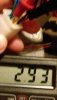
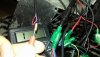
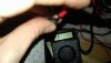
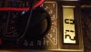
I bought a second hand pro rider e tourer and same thing happened. One day after being raining the Lcd panel stopped working. Still the trotter was working. I opened the LCD panel and dried it with a dryer, as it was wet inside. Then it started working for some secs and stopped again. The lights switched off and since then has not worked again.
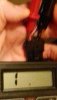
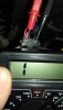
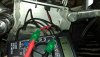
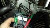
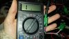
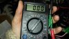
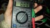
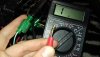
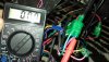
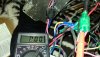
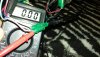
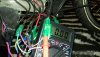
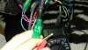
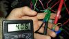
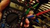
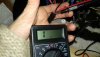
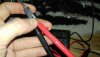
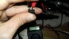
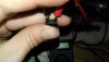
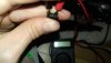
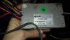
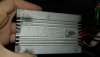
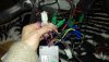
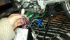
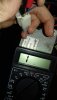
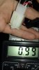
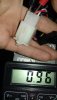
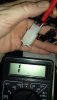
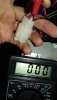
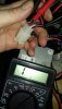
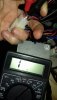
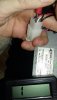
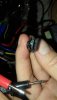
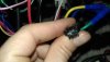
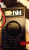
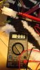
I opened the case where all the cables and the brushless motor is and checked them for any problem.
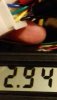
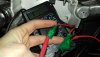
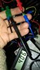
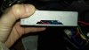
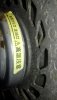
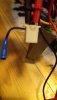
I bought another brushless motor 24v 250w and did not work.
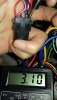
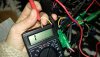
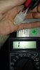
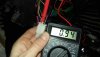
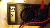
I think that I made a mistake as this should be 36v 250w, but I cannot see the voltage in the old brushless motor.
Anyone who could help me with any ideas, please.
I am pretty upset and desperate with 2 electric bikes that does not work.
Thanks
Belén
 
Last edited:

vfr400

Esteemed Pedelecer
Jun 12, 2011
9,822
3,986
Basildon
Motors are very reliable. When your bike doesn't work, you need to find the fault, not change the motor. The fault is nearly always in the control system or the battery, not the motor. To find the fault, all you need is a multi-meter.


We can help you if you show us photos of the control panel on the handlebars and the motor controller with all its wires and connectors clearly shown.
 
  • Like
Reactions: Nealh

Belen

Pedelecer
Aug 25, 2016
58
0
45
Bristol, uk
Motors are very reliable. When your bike doesn't work, you need to find the fault, not change the motor. The fault is nearly always in the control system or the battery, not the motor. To find the fault, all you need is a multi-meter.


We can help you if you show us photos of the control panel on the handlebars and the motor controller with all its wires and connectors clearly shown.

Hi there,
I have a voltmeter already, :) and I have been testing the cables, but I am not sure what should I test honestly, and how to know if it is working. I was watching some videos about this. The thing is from the cables coming where the battery is I had some measurements. But when I was measuring the cables coming from the brushless motor, nothing changed in the voltmeter.
So I ordered a new brushless motor 36v 250w that will be coming next Monday.
I will open the cage and show the pictures. Could you let me know what should I measure, please?
Electricity is interesting but I do not understand it very well...
Thanks
Belén
 

Nealh

Esteemed Pedelecer
Aug 7, 2014
20,134
8,230
60
West Sx RH
With motors you aren't testing for terminal motor voltage but for hall sensor individual voltage (<5v) or wire resistance in the phase wiring to detect any issue.
A motor can be tested using manual hand rotation to feel for resistance whether there may be an issue.
As VFR has mentioned most hub issues are elsewhere, replacing components willy nilly is silly and expensive without knowing why. You need to be able to detect the route cause first.
 

Belen

Pedelecer
Aug 25, 2016
58
0
45
Bristol, uk
With motors you aren't testing for terminal motor voltage but for hall sensor individual voltage (<5v) or wire resistance in the phase wiring to detect any issue.
A motor can be tested using manual hand rotation to feel for resistance whether there may be an issue.
As VFR has mentioned most hub issues are elsewhere, replacing components willy nilly is silly and expensive without knowing why. You need to be able to detect the route cause first.


Hi there,
thanks for the help. I watched a video to see how to test the wires, because I had not idea...
I have the pics with the testing.
Would you be able to help?
Thanks
Belén
 

Attachments

Belen

Pedelecer
Aug 25, 2016
58
0
45
Bristol, uk
I continue with the rest of the pics...I can only download 10 at time.
 

Attachments

Belen

Pedelecer
Aug 25, 2016
58
0
45
Bristol, uk
More...
 

Attachments

Belen

Pedelecer
Aug 25, 2016
58
0
45
Bristol, uk
More. The pics are different. Every cable tested and screen tester results...
 

Attachments

Belen

Pedelecer
Aug 25, 2016
58
0
45
Bristol, uk
more testing
 

Attachments

Belen

Pedelecer
Aug 25, 2016
58
0
45
Bristol, uk
more testing...
You can see that one of the parts looks like burned
I tested the cables both sides
Still no idea what does means mates.
Would be helpful to know what to do with the cables and the meaning.
I guess that some does not work, but how can I know and what to do with those?
Thanks
Belén
 

Attachments

Nealh

Esteemed Pedelecer
Aug 7, 2014
20,134
8,230
60
West Sx RH
From what I see your tests mean very little as you are using the range for AC testing, the dial needs to be set for the DC testing to the left.
Also I can't really tell which wires you are testing without an explanation.
 

Nealh

Esteemed Pedelecer
Aug 7, 2014
20,134
8,230
60
West Sx RH

vfr400

Esteemed Pedelecer
Jun 12, 2011
9,822
3,986
Basildon
Stop watching Youtube videos and then wasting your time doing pointless tests.

Set your meter to 200v DC, which is when the pointer is in the 11 o'clock position. Disconnect all wires from the controller except the battery wires and the power wires that go to the control panel (red pink black connector).

Test 1. With the battery connected and switched on, measure between the black and the red on the connector that powers the LED panel (red pink black). Test by sticking the probes up the back of the connector while connected, not on the pins.

Test 2. Switch on the cntrol panel and measure between the pink and the black wires. Do not let the probes touch each other. Use the pink on the controller side of the connector and the black on the panel side.

Test 3. With the panel switched on and the red, green back connector disconnected. Measure between the red and the black on the controller side of that connector.

Test 4 Reconnect that connector and measure again

Report those resilts, then we can move you quickly to a solution.
 

Belen

Pedelecer
Aug 25, 2016
58
0
45
Bristol, uk
Hi Nealth and fvr,
I spent all my eve measuring yesterday. Thanks for telling me how to do it in a precise way. Internet is pointless when you do not what are you doing. I had the doubt about switching the battery or not.
So I have been during Fvr meassurements.
The results for test 1: 41.5
Test 2: 01.2
Test 3: I wondered if you were asking for the hall connector. And measured this. Disconnected: 00.0
Connected: 00.0
I am posting the pics to make sure that I did the wright thing.
 

vfr400

Esteemed Pedelecer
Jun 12, 2011
9,822
3,986
Basildon
Test 2 shows a fault. With the LED panel switched on, it should have shown 41.5v. Without that voltage, all the other tests will show zero because it's the pink wire that provides power to the controller, which in turn powers them with 5v.

Did the Control panel light up when you switched it on?

There is a way to enable some temporary function to your bike, even if the control panel is faulty. I'll explain that after you answer the question above.
 

Advertisers