Problem with PAS

championc

Finding my (electric) wheels
Jun 21, 2020
7
0
Hi all

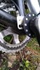
I really hope that someone can help me. I'm building an eBike for my Dad and everything works except the PAS.

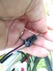
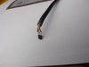
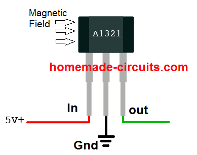
I checked the voltage and the Positive reads about 5v - with the signal cable also reading around 5v too (with the PAS disconnected). Should the signal cable not be nearer to zero ?

I tried disconnecting the signal cable from the connector block and connected the PAS. The signal cable coming back from the PAS was then fluctuating reading about 0.1v to -0.1v when I rotated the pedals.

So I don't know if I have a controller problem or a PAS problem - or the controller could have blown the PAS

Any info regarding voltage levels greatly received.

Thanks in advance
 

championc

Finding my (electric) wheels
Jun 21, 2020
7
0
It doesn't work at all. That's my problem.

I'm trying to figure out where the problem is
 

championc

Finding my (electric) wheels
Jun 21, 2020
7
0
brand X - AliExpress

On the cables, the PAS is the Yellow, Red and Blue, while the controller cables are Black, Pink/White and Yellow/Blue
 
Last edited:

vfr400

Esteemed Pedelecer
Jun 12, 2011
9,822
3,986
Basildon
One of three things might be causing your problem:
1 (most likely) Wrong connection sequence. You have to test with a meter which of the three wires from your controller is ground and which is 5v. You have to use continuity to a known ground and a known 5v. The third wire is then the signal wire. The red yellow and blue wires connected to brake sensors are always red 5v, blue signal and yellow ground, but I have seen on other 5v devices yellow signal and blue ground. The seller replied to a question that yellow was the signal, but he said black was ground instead of blue, so make whatever of that you can. Whatever is correct, if you can identify the 5v from your controller, then connect that to the red, which leaves two possibilities for the other two wires that you can try to see which works.
2. (strong possibility) Some of those sensors are just too sensitive for 12 magnets. The next magnet is affecting it before the first one has passed. The solution is to press out every other magnet to leave 6 magnets.
3. (least likely). Some of those sensors, especially ones that come with 12 magnets, are handed, so they only work on one side of the bike. before permanently installing a PAS, you should always test it in each of the 4 permutations of magnet side and rotation direction to see which of the 4 work. Testing means twizzling the magnet disk against the sensor. If it's handed, only one permutation works, so you have to make sure it's installed that way. Your sensor looks rather cheap and the schematic shows a single hall, so it's probably not a handed one, but always worth checking.

I would say that regardless of the above, your magnet disc needs to be flipped as you have the arrow of rotation in the correct direction, but that's normally for when it's installed on the other side. When you fit one to the left side, the arrow should point the wrong way unless you have a specifically left-handed one.

If I had to bet on a solution to your problem, I'd say you have to swap over the yellow and blue wires then flip the magnet disc. That's based on you saying that it didn't work when you pedal backwards.
 
Last edited:

championc

Finding my (electric) wheels
Jun 21, 2020
7
0
Thanks for taking the time to respond in such detail.

One of three things might be causing your problem:
1 (most likely) Wrong connection sequence. You have to test with a meter which of the three wires from your controller is ground and which is 5v. You have to use continuity to a known ground and a known 5v. The third wire is then the signal wire. The red yellow and blue wires connected to brake sensors are always red 5v, blue signal and yellow ground, but I have seen on other 5v devices yellow signal and blue ground. The seller replied to a question that yellow was the signal, but he said black was ground instead of blue, so make whatever of that you can. Whatever is correct, if you can identify the 5v from your controller, then connect that to the red, which leaves two possibilities for the other two wires that you can try to see which works.
As I mentioned in my first post, one wire was ground, while the other two were BOTH around 5v, which was why I was looking for guidance as to what those readings SHOULD be. I partially think that the Yellow/Blue should be very low - like the signal wire from the throttle

2. (strong possibility) Some of those sensors are just too sensitive for 12 magnets. The next magnet is affecting it before the first one has passed. The solution is to press out every other magnet to leave 6 magnets.
I could increase the distance the sensor from the magent ring too. but again, as mentioned in the first post, I tried by just connecting just the Pink/White positive and the negative only to the PAS and looked to measure the voltage returning on the signal wire - what should this be ?

3. (least likely). Some of those sensors, especially ones that come with 12 magnets, are handed, so they only work on one side of the bike. before permanently installing a PAS, you should always test it in each of the 4 permutations of magnet side and rotation direction to see which of the 4 work. Testing means twizzling the magnet disk against the sensor. If it's handed, only one permutation works, so you have to make sure it's installed that way. Your sensor looks rather cheap and the schematic shows a single hall, so it's probably not a handed one, but always worth checking.

I would say that regardless of the above, your magnet disc needs to be flipped as you have the arrow of rotation in the correct direction, but that's normally for when it's installed on the other side. When you fit one to the left side, the arrow should point the wrong way unless you have a specifically left-handed one.
You can see the arrow on the outside of the magnets ring, showing the intended direction. The arrow points towards the front wheel. There are no markings on the opposite side. If it was on the other side, it would point towards the back wheel

If I had to bet on a solution to your problem, I'd say you have to swap over the yellow and blue wires then flip the magnet disc. That's based on you saying that it didn't work when you pedal backwards.
The Black cable from the controller is the negative and the Yellow is the negative / Ground for the Hall Effect Sensor. I dismantled the sensor to check it. The center ground was suspect, so I resoldered it. The Red is the 5v and the Blue is the Signal
36324
Linear Hall-Effect Sensor - Working and Application Circuit ...
 

Advertisers