Rear Hub Spin Out - Cable Damage and Issues

portals

Esteemed Pedelecer
Jul 15, 2022
774
228
After adding two of the cheapo torque arms on my rear hub and redoing mechs so everything fitted together better (I think local bike guy tried to kill me on at least three occasions past cpl years..), I'd gotten a little cocky and stopped checking the rear hub before each trip.

Anyway it spun out the other night there, both torque arms did I suppose eventually their job and stopped axle falling out of dropouts however nuts both side were hand loose and the left side was getting close to edge of dropouts. The cable from hub axle to connector to battery got caught and damaged although it wasn't pulled out the controller socket.

Had designed a 3d printed torque arm but had been too lazy to get it metal cut as thought the two cheap torque arms would suffice...with hindsight...

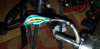
Shield was torn and you can see green phase power wire shielding is damaged. My understanding is that I have 9 wires in total:
Thick blue/green/yellow wires are phase power
Thin blue/green/yellow wires are phase sensors
Red/Black is +ve/-ve for motor board
White is speed sensor
(No 10th thermistor wire)

61940
61935


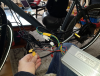
Controller is this (17A continuous, 35A peak).
61936


Display:
61937


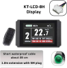
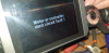
When I power on no error on display however when I push thumb throttle I get this error so assumption is that wiring is damaged either in the hub harness cable or actually inside the motor and shorting. If it was thick wires I might expect smoke but not for thin wire sensor short but could be the red/black power? I dunno.
61938


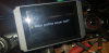
When I unplug the hub and use throttle I get this error which I've seen before when I was fitting in USB C and knocked lose the thin wire connector so this error is to be expected when hub is not plugged in?
61939


So any suggestions as to way forward?

Probably I will have to strip off all the shielding to check wires however if it's inside the hub then it will be going in the bin (never bought the big gear puller in end as I like 10 fingers). I got bearing redone few months ago then the fecker started clicking again few weeks ago, have been thinking of downgrading hub however I would like to understand if there are any suggested tests I can do to try and narrow down issue? I can check sensor wires by manually spinning wheel and probing controller, what else can I test? I'm assuming the controller will be OK as it has short circuit protection.

Any thought welcome. Thanks
 

portals

Esteemed Pedelecer
Jul 15, 2022
774
228
Both rounded out, avoid

61941
61942


Shitty clamps came of even worse...drive side (bottom hose clamp) was getting there...
61943
 

saneagle

Esteemed Pedelecer
Oct 10, 2010
8,398
3,824
Telford
Were you using regen?

Use a meter to check the cables rather than strip them down. You can also do the rotation test. If any phase wires are touching, it's hard to turn the wheel. Do it when disconnected and connected to the controller (switched off) in case the short is from a blown MOSFET.
 

portals

Esteemed Pedelecer
Jul 15, 2022
774
228
How can i check the cables though, I suspect the issue is in cable or hub.

I can test from where the wires are visible upstream to controller for continuity however if the short is downstream at axle end or inside hub then there is little to test against?
 

saneagle

Esteemed Pedelecer
Oct 10, 2010
8,398
3,824
Telford
How can i check the cables though, I suspect the issue is in cable or hub.

I can test from where the wires are visible upstream to controller for continuity however if the short is downstream at axle end or inside hub then there is little to test against?
Set your meter to continuity if it has it, otherwise resistance. Check continuity between each phase wire and the axle, each hall wire to the axle, each hall wire to each phase wire, and each hall wire to each other hall wire. The resistance between each pair of phase wires should be low but not zero. Unfortunately, many multi-meters can't measure that low, but if yours can, somewhere about 0.3 Ohms.
 

portals

Esteemed Pedelecer
Jul 15, 2022
774
228
Set your meter to continuity if it has it, otherwise resistance.
It has continuity setting.


Check continuity between each phase wire and the axle,

Results:
Blue Phase-axle: no continuity
Green Phase-axle: no continuity
Yellow Phase-axle: no continuity


each hall wire to the axle,
Results:
Blue Hall - axle: no continuity
Green Hall - axle: no continuity
Yellow Hall - axle: no continuity


each hall wire to each phase wire,
Results:
Blue Hall - Green Phase: yes continuity
Blue Hall - Yellow Phase: yes continuity
Green Hall - Blue Phase: yes continuity
Green Hall - Yellow Phase: yes continuity
Yellow Hall - Blue Phase: yes continuity
Yellow Hall - Green Phase: yes continuity


and each hall wire to each other hall wire.
Results:
Blue Hall - Green Hall: no continuity
Blue Hall - Yellow Hall: no continuity
Green Hall - Blue Hall: no continuity
Green Hall - Yellow Hall: no continuity
Yellow Hall - Blue Hall: no continuity
Yellow Hall - Green Hall: no continuity


The resistance between each pair of phase wires should be low but not zero. Unfortunately, many multi-meters can't measure that low, but if yours can, somewhere about 0.3 Ohms.
Do you mean that if I didn't have continuity feature so had to use resistance to measure continuity it should be low around 0.3 ohms an so this 'counts' as negligible therefore we have continuity? Or something else?


The resistance between each pair of phase wires should be low but not zero.
Do you mean resistance or continuity (or same difference) between: Blue Phase power and Blue Hall wires/Green Phase power and Green Hall wires/Yellow Phase power and Yellow Hall wires should be 0.3 ohms

Results:
Blue Hall - Blue Phase: yes continuity
Green Hall - Green Phase: yes continuity
Yellow Hall - Yellow Phase: yes continuity

Thanks
 

matthewslack

Esteemed Pedelecer
Nov 26, 2021
2,399
1,604
The phase wires are completely separate from the hall sensor circuitry. There should be no continuity between any of the six small pin wires and any of the three big pin wires, when measured at the disconnected motor connector.

The big phase wires only connect to the motor phase windings.

The six small wires, green blue yellow phase signals, red and black 5V and ground, and white speed sensor, share the connector but all go to the hall sensor circuit board.

Ard you really measuring hall to phase continuity, or is that a mistake for phase to phase continuity?

I assume you are measuring at the motor cable, not the controller cable.
 

portals

Esteemed Pedelecer
Jul 15, 2022
774
228
I tested with everything plugged in to controller cable but battery switched off.

I assume you are measuring at the motor cable, not the controller cable.
I am testing at the controller cable end by shoving the probes in to the gaps you can see. The cable from motor is plugged in to the controller cable and the other end of controller cable goes to the two connector blocks below in to actual controller.

61957


To test at motor end I'd need to make cuts in the wires here at hub end to probe everything as no large gear puller to take motor apart and test directly on motor - would make no difference anyway when testing continuity?
61958


So far it would appear that there is no continuity (short) between the phase power (thick wires) and ground and no short between hall (thin wires) and ground so that's good and implies there cables are OK with no damage?

However if there is continuity between phase and hall as per results above, then that's probably not good and might imply controller has taken a dose of Amps on hall line and is stuffed, what could be shorting them internally, blown MOSFET(s) shouldn't do this?

Thanks
 

matthewslack

Esteemed Pedelecer
Nov 26, 2021
2,399
1,604
The two basic tests of MOSFETs in the controller and hall sensors in the motor are performed with everything else disconnected.

I would do those tests in the normal way rather than try to interpret the results of tests with things connected.


Nealh

Esteemed Pedelecer
Aug 7, 2014
21,399
8,746
61
West Sx RH
With a spin out one can cause motor phase wire short, blown motor Halls or blown controller mosfet .
Hard motor resistance with controller connected (manually turn wheel) = pahse short , eithe motor wiring or mosfets.
If one disconnects the controller and still hard resistance , then motor wire shorted .
If disconnected and resistance frees up then controller mosfet/s shorted
(one can also test mosfets with a meter on the ohms scale).

For motor Hall sensors one will need the battery an dcontroller connected for 5v power supply , then test for 5v on the motor Halls.
 

saneagle

Esteemed Pedelecer
Oct 10, 2010
8,398
3,824
Telford
It has continuity setting.
Your results don't make sense. You must have made a mistake or something changed during the measurements. If both blue and yellow halls have continuity to the green phase wires, then they must have continuity between each other.

When I said "resistance" above, I meant resistance in Ohms.