

I can't understand any of that. The replacement controller was replaced, the controller you wanted to put in is out, and the one you took out is in. Is that it? Not that it matters because you still haven't explained what the problem is. Did something catch fire? Was your motor going too fast? Did the motor run by itself? What inspired you to come to the conclusion that the controller that you may or may not have replaced with one that might or might not be faulty is faulty?
Help! Replacement electronic controller required
- Thread starter Tony Emerson
- Start date
Many apologies for the confusion
To clarify:
My wife and I both have a Freego Hawk bike and these have identical controllers.
Whilst in use her machine stopped working – i.e. would not respond to pedaling or to rotation of the hand throttle. There was no obvious reason – e.g. smoke, fire, motor run away, etc. etc. - for this failure. All the LEDs on the control panel remained illuminated.
From this I concluded that the controller on her bike was at fault.
As my bike was still working, I took out its controller and replaced it with the faulty unit from her bike.
After this change over my machine also stopped working – i.e. would not respond to pedaling or to rotation of the hand throttle.
This confirmed that the controller on my wife’s bike is faulty.
What caused it to fail is not so clear. It could be: (1) break down of an internal component alone, or (2) possibly in combination with a failure in the connected electrical equipment (motor, wiring etc.)
I think it is most likely to be (1). Are there any tests I can do to establish whether it is (2)?
In the meantime I am going to need a new controller. To simplify the change over, I would prefer this to be as close to the existing unit as possible. Also cheap, as if I get it wrong, can live with the loss!
Grateful if you could help with Internet links to a suitable controller for me.
fault finding on bikes with LED panel:
1. unplug pedal assist sensor and brake switches
2. test the motor with just the throttle
If test passes, connect the brake switches then retest
if test passes, connect the pedal sensor then retest
Fault finding on bikes with LCD:
1. unplug pedal assist sensor, throttle and brake switches
2. press and hold the - button to test the motor in walk mode
If test passes, connect the brake switches then retest
if test passes, connect the throttle then retest
if test passes, connect the pedal sensor then retest

OK. That's understandable and makes sense. Controllers are pretty reliable. I think that I've only ever seen five faults in controllers in many years of testing and fixing electric bikes.Many apologies for the confusion
To clarify:
My wife and I both have a Freego Hawk bike and these have identical controllers.
Whilst in use her machine stopped working – i.e. would not respond to pedaling or to rotation of the hand throttle. There was no obvious reason – e.g. smoke, fire, motor run away, etc. etc. - for this failure. All the LEDs on the control panel remained illuminated.
From this I concluded that the controller on her bike was at fault.
As my bike was still working, I took out its controller and replaced it with the faulty unit from her bike.
After this change over my machine also stopped working – i.e. would not respond to pedaling or to rotation of the hand throttle.
This confirmed that the controller on my wife’s bike is faulty.
What caused it to fail is not so clear. It could be: (1) break down of an internal component alone, or (2) possibly in combination with a failure in the connected electrical equipment (motor, wiring etc.)
I think it is most likely to be (1). Are there any tests I can do to establish whether it is (2)?
In the meantime I am going to need a new controller. To simplify the change over, I would prefer this to be as close to the existing unit as possible. Also cheap, as if I get it wrong, can live with the loss!
Grateful if you could help with Internet links to a suitable controller for me.
fault 1.
Battery connected the wrong way round. It often blows the shunt and main capacitor/s, and sometimes blows other components. If you didn't fit a new battery, this fault can't be possible. It's not worth attempting to repair this fault.
fault 2.
Short circuit on the 5v rail blows the 5v regulator. This is easy to repair by replacing the regulator. You can test it by measuring between the red and black wires on the throttle, pedal sensor or motor hall sensors with the controller powered on. You should see 5v. The problem is caused by water getting in the throttle or any of the connectors with 5v on them. Salty water of winter roads is the worst..
fault 3.
Software annihilated. This happens when you get water in a throttle that has battery indicators in it or in any connector that has battery voltage next to 5v. This fault is nearly impossible to test. You can only determine it by a process of elimination and inspection. If you had fault 2, you might have fault 3 as well because they have the same cause. You also get this fault when messing about with connectors when you don't know what your doing. People buy a new throttle with mismatching connectors and then try and get it working by experimentation, connecting each combination of wires. If you connect the battery wire to the 5v, it blows the main CPU and can blow any of the 5v devices on the 5v rail. This fault cannot be repaired.
fault 4.
Blown MOSFET/s. This happens when you draw too much current for too long, like riding your bike too slow with full power. Low speed and high power is very bad for a bike with a hub-motor. This fault is very easy to test. Disconnect the controller and measure the resistance between the battery positive wire and each of the three motor phase (power) wires, then again for the negative battery wire to get six results. Each set of three should be the same as each other and in the range 7K to 14K. This fault is not worth repairing.
fault 5.
Blown transistor that switches on the lights. Some controllers have a lights switch function and a connector that provides the battery voltage to connect the lights too. If you connect lights that draw too much current or get a short circuit in the cable to the lights, it blows the transistor and it can do other consequential damage. In the cases that the controller was still operational, the lights stayed on all the time. It's not easy to test, but you can normally see the burnt transistor on the controller's PCB. You follow the wires from the lights connector to where it's attached to the PCB , and the transistor will most likely be sitting nearby.
Last edited:
Thanks for the comprehensive response
As it was (for me) the easiest to do, tested for fault 4 (blown MOSFETs) first, with the following results:
Motor phase Blue to battery +ve - resistance = 10.88kΏ
Motor phase Blue to battery -ve - resistance = 6.04kΏ
Motor phase Yellow to battery +ve - resistance = 10.88kΏ
Motor phase Yellow to battery -ve - resistance = 6.04kΏ
Motor phase Green to battery +ve - resistance = 1.6Ώ.
Motor phase Green to battery -ve - resistance = 3.73kΏ
From which it appears that the “Green” MOSFET has failed,
In light of this result and, as you have indicated that this failure is not worth repairing, did not attempt the other tests. But can do if necessary
On this basis seems my wife’s machine needs a new controller. So would be grateful if you could advise Internet links to a suitable replacement (if possible (necessary?) with matching connectors, and also sacrificially cheap!).
Controllers with the flat connector for the halls aren't that common, and even if you did find one, many of the other connectors wouldn't match. Look back at post #15. I still stand by that advice and recommend it as the best option. Apart from installing the new PAS and speed sensor, you have to cut the hall sensor connectors off and solder the wires directly together and insulate with heatshrink sleeves.
You have a special LED panel that won't work with most controllers, so if you do go for a cheap one, you have to buy one with an LED panel.
You have a special LED panel that won't work with most controllers, so if you do go for a cheap one, you have to buy one with an LED panel.
He's already determined that he has a blown mosfet in the controller. His bike is different to most in that his LED panel converts the PAS signal into a throttle signal, which means that some of your procedure is not valid.fault finding on bikes with LED panel:
1. unplug pedal assist sensor and brake switches
2. test the motor with just the throttle
If test passes, connect the brake switches then retest
if test passes, connect the pedal sensor then retest
Fault finding on bikes with LCD:
1. unplug pedal assist sensor, throttle and brake switches
2. press and hold the - button to test the motor in walk mode
If test passes, connect the brake switches then retest
if test passes, connect the throttle then retest
if test passes, connect the pedal sensor then retest
at the time of my post, he has not been able to identified the fault on his controller.He's already determined that he has a blown mosfet in the controller. His bike is different to most in that his LED panel converts the PAS signal into a throttle signal, which means that some of your procedure is not valid.
This confirmed that the controller on my wife’s bike is faulty.
What caused it to fail is not so clear. It could be: (1) break down of an internal component alone, or (2) possibly in combination with a failure in the connected electrical equipment (motor, wiring etc.)
I think it is most likely to be (1). Are there any tests I can do to establish whether it is (2)?
Sorry, I have three different versions of the page open, so on one it looked like yours was the last post.at the time of my post, he has not been able to identified the fault on his controller.
In post 24, fault 4, you refer to the problem of high power selection and slow bike speed leading to MOSFET failure. It appears from this that exchanging the failed controller for a similar design unit would leave me with a replacement unit also prone to MOSFET failure.
Would a more modern controller such as you have recommended (post 15), avoid this problem?
I ask because we live in a particularly hilly area for which HI power selection and slow bike speed are an unavoidable and frequent occurrence.
Your comments welcomed.
Would a more modern controller such as you have recommended (post 15), avoid this problem?
I ask because we live in a particularly hilly area for which HI power selection and slow bike speed are an unavoidable and frequent occurrence.
Your comments welcomed.
Controllers come in differing case sizes, the large the case the more fets. More mosfets will deal with the higher amp load that can be applied as well as dealing with greater heat issues. Typically sensored ones use 6 fets for controllers rated up to 20a or non-sensored use 9 fets. A 22/25a sensored controller uses 9 fets so can handle the amp draw/heat better, the larger controllers will use 12 fets or more. There is no reason why you can't use a better higher rated controller esp if able to limit the amp draw via lcd3 as in the case with using KT stuff so that you don't draw more then the battery can supply.
Even the popular well used 6 fet KT suffers from heat if used in high power /slow speed, the unit will cut out by way of thermal cut out until it cools down. The cut out is the fets getting to hot and temporarily they short out when their max op temp is reached, they switch again once cooled cool down. My answer has been to upgrade to a 9 fet controller to help eradicate the problem and so far it has not arisen.
Long term heat damage will cause a/the fet/s to fail rendering the bike albeit dead until controller is replaced.
Thanks for the info'/advice.
Have frequently experienced the thermal cutting in/out on the Isle of Skye's hills. Indications of trouble to come!
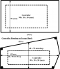
Having had to "shoehorn" a 6 x MOSFET unit plus wires and connectors into the existing housing (see sketch below) seems unlikely it will accommodate a 9 x MOSFET unit.
Maybe you have/know of a ready made solution?
Your comments welcomed
(And if not: we are moving home to a less hilly area, so am minded to stick with what we have, and picking less demanding routes. Disappointing, but less demanding than embarking on a D-I-Y solution involving waterproofing and re-wiring!)
Have frequently experienced the thermal cutting in/out on the Isle of Skye's hills. Indications of trouble to come!
Having had to "shoehorn" a 6 x MOSFET unit plus wires and connectors into the existing housing (see sketch below) seems unlikely it will accommodate a 9 x MOSFET unit.
Maybe you have/know of a ready made solution?
Your comments welcomed
(And if not: we are moving home to a less hilly area, so am minded to stick with what we have, and picking less demanding routes. Disappointing, but less demanding than embarking on a D-I-Y solution involving waterproofing and re-wiring!)
Noted thanks
Will get the PSW controller and bits, and take it - with help - from there..........................
Will get the PSW controller and bits, and take it - with help - from there..........................
Firstly must apologise for going off line for a while, but got swamped with domestic imperatives various, so regret bike problem had to go to the back burner.
Time not entirely wasted, as was able to draw up the attached wiring diagram. Thought this might help in the process of resolving which connectors go where etc., when exchanging the Freego and WSP units.
Will be in touch once I have the WSP controller and accessories
Time not entirely wasted, as was able to draw up the attached wiring diagram. Thought this might help in the process of resolving which connectors go where etc., when exchanging the Freego and WSP units.
Will be in touch once I have the WSP controller and accessories
Attachments
-
585.3 KB Views: 28
STOP PRESS: Have located a TV electrician who thinks he may be able to replace the damaged MOSFET.
Not too sure of a successful outcome, but seemed worth a try, so purchase of the PSW Power unit on hold for now
Not too sure of a successful outcome, but seemed worth a try, so purchase of the PSW Power unit on hold for now
It would have been better to show individual wires in your diagram because when you clump them together in a single line, it doesn't show the unique way that the LED panel converts the pedal assist signal into a throttle signal.
You have about a 50/50 chance of success by replacing the blown MOSFET. Good luck!
You have about a 50/50 chance of success by replacing the blown MOSFET. Good luck!
Your 50/50 well founded! All the LEDs lit up, but that was it!
Can but agree re the wiring diagram, but limited it to what I could see as a reasonable basis for identifying a need to dismantle further if/when need arises.
Before ordering same, grateful some more advice on the PSW controllers: the 15A unit comes with a full selection of additional features (in particular: throttle; speed; brake & PAS), where as the 17A (preferred - see 33 above) offers only throttle OR PAS.
64$ question is which to get? And with what addition(s)?
You need the LCD and the wheel speed sensor. Both controllers should work with your PAS and throttle. Their ones have the right connectors and guarantee compatibility. I always think that they're so cheap when you buy them with the controller that they're always worth buying in case of any problems, and they're always useful as spares.
The 15 amp one is 24v/36v and the 17A one is 36v/48v. Apart from that, the listings are identical. I don't know which ones you've been looking at.
The 15 amp one is 24v/36v and the 17A one is 36v/48v. Apart from that, the listings are identical. I don't know which ones you've been looking at.
And the good news is: repeated the installation/connection process for the repaired controller and it worked!
Awaiting opportunity to give the bike a thorough test run, but so far looking good. Will report outcome
Awaiting opportunity to give the bike a thorough test run, but so far looking good. Will report outcome