People often ask, “can I put two packs in parallel to increase capacity and reduce strain on each battery pack?” Yes you can, but you need to make sure that the two packs are of a similar voltage before connecting them. Also, if you disconnect one pack, the socket will still be live from the other battery, which could be hazardous. A way of overcoming this issue is to use blocking diodes, so that current cannot flow from one pack to the other. Unfortunately, normal diodes induce a voltage drop of more than 0.5V, which means that significant power is lost and waste heat generated. However, we can utilise Schottky diodes (widely used in the solar power industry) which only induce a voltage drop of 0.1 to 0.2 V to reduce this power loss to an acceptable level.
This is a concept that occurred to me a long time ago, but I didn’t try it out until quite recently, when I suggested it in a thread a couple of months back and forum member “Sturmey” said he had already tried it and it worked well for him. So I do want to acknowledge Sturmey for that, I don't claim to be the first to do this.
I don’t want to disparage anyone’s technical ability, but I will say that although this is a fairly simple thing to do, if you are not sure what you are doing, get some help. The power packs used on e-bikes can deliver a big punch if you do not respect them and, here we are dealing with two packs together. Power packs are some of the most expensive bits of e-bike kit and you could destroy two in one go…not to mention starting a fire you can’t put out easily and the fact that you could burn yourself quite badly if you do not do things carefully and pay attention to what you are doing.
To make a Schottky Diode parallel pack adaptor, you need suitable wire (eg silicone coated 12AWG) 2 suitable Schottky diodes, a heatsink, two male XT60 connectors and one female XT60 connector.
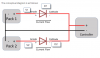
The conceptual diagram is as follows:
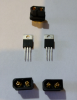
The diodes I used were 60A 100V (MBR60100CT), which is probably overkill, but I prefer to over engineer a bit, as you don’t want this to be the weak link in the chain and you might want to use it for a higher power project later. These diodes are actually dual diodes in one package. We will use two of them in parallel. As each diode in the 60A package is 30A, in principle you could get away with just using one of these components and using the two diodes inside it for this application, ie, running a 15 A controller (using one half of the dual diode component for each battery pack). However, for me that seemed a bit marginal as the current trip in my pack is 30A and the BMS is rated to 40A. So, I used two components to give me 60A per pack, which would give plenty of margin for safety.
A modest heatsink is needed as the voltage drop from these diodes means some power is consumed. I measured this to be 0.18V for these diodes, so if drawing 15A, it means 2.7W is dissipated in the diodes, which needs to go somewhere.
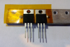
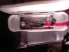
The centre connection to the dual diode is the common cathode, and this also is connected to the metal tab on the diode package. As I was soldering the dual anode pins together to make a 60A device, I decided to cut off the middle common cathode connection and solder onto the tab for the cathode connection (my soldering was a bit messy, but you will be able to do a better job") ). You need to take care to isolate the cathode from the heatsink with something like this polyimide tape, and ensure that the solder does not come into contact with the heatsink screws. It’s a bit fiddly, but it can be done (there is also a plastic insulator under the screws you can't see in the picture). The reason for this is that you do not want your heatsink to be at battery voltage, in case it shorts against anything.
). You need to take care to isolate the cathode from the heatsink with something like this polyimide tape, and ensure that the solder does not come into contact with the heatsink screws. It’s a bit fiddly, but it can be done (there is also a plastic insulator under the screws you can't see in the picture). The reason for this is that you do not want your heatsink to be at battery voltage, in case it shorts against anything.
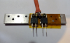
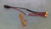
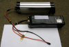
Now you can solder on your connections, tidy it up with some shrinkwrap and put on the XT60 connectors. For safety, use male connectors on the battery side and a female connector to go to the controller.
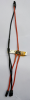
Now you are ready to connect. Here I have two battery packs. One is at 40.6 V and the other at 38.8V.
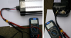
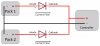
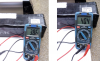
Here they are connected to the Schottky Diode Adaptor:
When both packs are connected and switched on, the voltage read by the voltmeter is approx. 0.2V lower than the most charged pack (in this case the pack at 40.6V, giving 40.4 V). When only one pack is switched on, or connected, the voltage is approx. 0.2 V lower than the pack voltage (ie in this case 40.4 or 38.6V).
So there you have it, an adaptor cable that allows you to have two packs connected together, without having to worry about matching their state of charge, or having a live connector present when one pack is removed. Not the most elegant or efficient solution, but simple and effective. I think the electronic experts out there will be able to make a little voltage comparator circuit that switches on or off a couple of MOSFETS or similar, which would be a lot more efficient, but I think this is a nice simple fix that most people could easily put together.
This is a concept that occurred to me a long time ago, but I didn’t try it out until quite recently, when I suggested it in a thread a couple of months back and forum member “Sturmey” said he had already tried it and it worked well for him. So I do want to acknowledge Sturmey for that, I don't claim to be the first to do this.
I don’t want to disparage anyone’s technical ability, but I will say that although this is a fairly simple thing to do, if you are not sure what you are doing, get some help. The power packs used on e-bikes can deliver a big punch if you do not respect them and, here we are dealing with two packs together. Power packs are some of the most expensive bits of e-bike kit and you could destroy two in one go…not to mention starting a fire you can’t put out easily and the fact that you could burn yourself quite badly if you do not do things carefully and pay attention to what you are doing.
To make a Schottky Diode parallel pack adaptor, you need suitable wire (eg silicone coated 12AWG) 2 suitable Schottky diodes, a heatsink, two male XT60 connectors and one female XT60 connector.
The conceptual diagram is as follows:
The diodes I used were 60A 100V (MBR60100CT), which is probably overkill, but I prefer to over engineer a bit, as you don’t want this to be the weak link in the chain and you might want to use it for a higher power project later. These diodes are actually dual diodes in one package. We will use two of them in parallel. As each diode in the 60A package is 30A, in principle you could get away with just using one of these components and using the two diodes inside it for this application, ie, running a 15 A controller (using one half of the dual diode component for each battery pack). However, for me that seemed a bit marginal as the current trip in my pack is 30A and the BMS is rated to 40A. So, I used two components to give me 60A per pack, which would give plenty of margin for safety.
A modest heatsink is needed as the voltage drop from these diodes means some power is consumed. I measured this to be 0.18V for these diodes, so if drawing 15A, it means 2.7W is dissipated in the diodes, which needs to go somewhere.
The centre connection to the dual diode is the common cathode, and this also is connected to the metal tab on the diode package. As I was soldering the dual anode pins together to make a 60A device, I decided to cut off the middle common cathode connection and solder onto the tab for the cathode connection (my soldering was a bit messy, but you will be able to do a better job
). You need to take care to isolate the cathode from the heatsink with something like this polyimide tape, and ensure that the solder does not come into contact with the heatsink screws. It’s a bit fiddly, but it can be done (there is also a plastic insulator under the screws you can't see in the picture). The reason for this is that you do not want your heatsink to be at battery voltage, in case it shorts against anything.Now you can solder on your connections, tidy it up with some shrinkwrap and put on the XT60 connectors. For safety, use male connectors on the battery side and a female connector to go to the controller.
Now you are ready to connect. Here I have two battery packs. One is at 40.6 V and the other at 38.8V.
Here they are connected to the Schottky Diode Adaptor:
When both packs are connected and switched on, the voltage read by the voltmeter is approx. 0.2V lower than the most charged pack (in this case the pack at 40.6V, giving 40.4 V). When only one pack is switched on, or connected, the voltage is approx. 0.2 V lower than the pack voltage (ie in this case 40.4 or 38.6V).
So there you have it, an adaptor cable that allows you to have two packs connected together, without having to worry about matching their state of charge, or having a live connector present when one pack is removed. Not the most elegant or efficient solution, but simple and effective. I think the electronic experts out there will be able to make a little voltage comparator circuit that switches on or off a couple of MOSFETS or similar, which would be a lot more efficient, but I think this is a nice simple fix that most people could easily put together.