5v on both indicate they are sending info, either a signal or reading. How they were connected to the original battery no one really knows with out being able to see inside one.
We know red is the v+ supply from the battery an we know the black is the v- supply, I suspect they may have all been connected to a small pcb. White is most often used as a speed wire but in this case it and orange were probably just used for battery voltage/level indicator.
A real pic of your sketch may show us more of how or where they go or are connected to in the controller.
Other wise you will have to just insulate the two wires properly and if you want any real time voltage reading, rig up a separate cheap voltage meter vai the red and black wire to monitor usage.

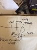 Hi I have just bought a ave ebike without a battery I have connected my dolphin battery to the red and black cables in the controller ever thing works except the battery level indicator always shows empty. The photo is the front of the controller layout. Does anyone know what the unused connections should connect to. Thanks Chris
 MTF Enterprises announces acquisition of EMU Electric Bikes
 Wisper 806T folding bike wins Which? ‘Best Buy’
 Sustrans calls for protected cycle lanes
 Amazon launch their first UK e-cargo micromobility hub