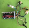
Do you have the control panel that goes with it? That will give you a clue to whether that's a throttle or PAS connector.
Alternatively, if you put power on the battery wires and connect the motor, then connect the control panel and switch it on if you have it, or join the orange to the red wire in the control panel connector if you don't have it. Now, if you bridge the red to the green wire in that three pin connector and the motor goes full speed, it's for a throttle. If the nmotor doesn't go, tap those wires together as frequenly as you can. if that makes the motor go, it's for a normal pedal sensor.
Orange and white are battery voltage that switches on when you switch on the control panel -for lights or whatever you want. Red and black is also battery voltage. it stays on as long as the battery is connected and switched on. Black and white is probably the brake connector. The rest are obvious.

 MTF Enterprises announces acquisition of EMU Electric Bikes
 Wisper 806T folding bike wins Which? ‘Best Buy’
 Sustrans calls for protected cycle lanes
 Amazon launch their first UK e-cargo micromobility hub