mike thompson
Members
-
Joined
-
Last visited
-
I have done this with an oscilloscope, I figured I should see a some combination of voltages across the phases depending on which sector I had set up with the hall sensors. There are I believe 6 combinations of 5v, 0v, across the 3 sensors you can use like a 3 bit binary number to represent the 6 of 60 degree rotation sectors, you cant use 5v,5v,5v or 0v,0v,0v.Thing I am not sure of is what happens when wheel is stationary? How does it get going? I just see 0v on all 3 phases
-
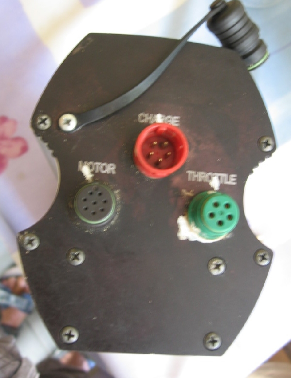
Thanks, I uploaded a file (coveconn.jpg), new to forum so not sure where to view. There are 3 connectors, red one just for charging. The motor connector has 8 pins: 3 phase, 3 hall sensor and 5v, 0v for hall power. The green throttle connector uses four pins: 5v, 0v, throttle input, and 36v ( presumably to show charged state on throttle leds). I am putting 5v across throttle input and 0v pin to simulate full throttle. On the motor connector I put 5v , 0v, 0v combination on the hall sensor pins to simulate a rotation position ( ground attached to the 0v pin of the hall sensor power ground pin so grounds are linked). I figured this represents a stationary state of a wheel so on twist and go I should see something on one of the phase wires trying to turn the motor? I appreciate I really need a throttle and a brushless motor in a wheel, situation is I inherited controller with good battery and trying to decide if its worth buying the rest.

-
Thanks for replies. My conv-e is older , does not have the yellow connector. When the wheel is stopped the hall sensors must have a fixed voltage , a combination of 5v, 0v, 0v to represent the section it is stopped at , therefore a phase voltage surely must occur to start the motor. I have an oscilloscope. I have applied 5v to the throttle input of the controller so shouldnt need a throttle. By checking the resistance to ground and to power on each phase pin they are all 10k, the fets are not blown. All 3 phases aee showing 0v
-
I am not testing the hall sensors, I dont have a wheel or a motor. I am simulating the output of the hall sensors by putting a voltage into the controller on the correct pins. The conv -e does not have pedal sensor input. I am trying to understand why there would not be a voltage on the phase pins if a voltage is put on the throttle input pin ( I dont have a throttle either )
-
Ive acquired a conv-e controller without the motor. Id like to check it works. The battery charges and all the cells have good voltage. I figured if I put 5v and 0v on the hall sensor pins ( not 000 or 555 ) and put 5v on the throttle pin with earth connected I should see volts out on the g, b, y phase pins but I dont, they are all 0v. Does it need a load to work.?