Slightlypedantic
Members
-
Joined
-
Last visited
Everything posted by Slightlypedantic
-
I've been looking online for explanations of PWM current control. Although I haven't found anything e-bike specific, I keep coming across graphs like Fig 2 of the Wikipedia article "Pulse-width Modulation": Figure 2 "The simplest way to generate a PWM signal is the inter-sective method, which requires only a sawtooth or a triangle waveform (easily generated using a simple oscillator) and a comparator. When the value of the reference signal (the red sine wave in figure 2) is more than the modulation waveform (blue), the PWM signal (magenta) is in the high state, otherwise it is in the low state." The saw-tooth or triangular waveform determines the frequency of the PWM pulses, say 20kHz. The sine-wave frequency and timing are determined and synchronised using the motor Hall sensor outputs. Sine-wave frequency is likely to be less than 1kHz (c. 550Hz max in my motor) depending upon motor design, reduction gearing and road speed. This implies at least 20 PWM pulses per sine-wave cycle: 10 pulses in the upward part and 10 pulses in the downward part, with the actual number of pulses per cycle increasing as rpm falls. The sine-wave amplitude (height) could be determined by the current required for a particular PAS setting and controlled by a feedback loop. The red line on the graph shows full power. For lower PAS levels the red sine-wave curve would be correspondingly flatter, with the maximum pulses widths being reduced accordingly. At PAS level 1 the current required might be, for example, 20% of the maximum current allowed by the controller. This could be interpreted as PWM pulses being 20% on and 80% off. This means there is plenty of scope to increase the pulse widths so as to maintain current and torque as back emf increases. This could be achieved simply by varying the sine-wave amplitude (height) via a feedback loop. It's probably more complicated than that, but hopefully these basic ideas are somewhere near the mark.

-
Interesting graph... Since the current is constant for each power level, regardless of speed/back emf variations, the controller must be compensating by increasing the pulse widths to maintain a constant current. Once speed/back emf have increased to the point where current is being supplied 100% of the time, further compensation is not possible and current declines according to any further increase in back emf.
-
Looks a useful web site. Unfortunately they are out of 1x spiders atm, but I'm not in a hurry and can wait.
-
I have a similar problem: I have a Haibike Trekking 6 i630 (2022 model) with Yamaha PW-ST motor and 38T chain-ring. The chain-ring is dished and all in one piece; it slides straight onto the motor shaft - no separate spider. The chain-line appears to be 52mm, and the OLD is 148mm. I would like to raise the gearing, as I spend a lot of time in the top two or three gears. With a 10 speed 11-46T cassette, hill-climbing is fine and I don't use bottom gear or high power very often. As far as I can tell, I'll need a spider and separate chain-ring, perhaps 40T or 42T. I don't know whether going larger would compromise hill-climbing, although the motor does appear pretty strong. I've seen spiders for other versions of the PW motor but not specifically PW-ST, and they are out of stock anyway. Is any PW-** spider likely to fit and have the correct chain-line? What size chain-ring should I fit? Where can I buy the parts? Any thoughts or ideas, anyone? Am I on the right track, or heading for a pitfall?! Thanks in advance.
-
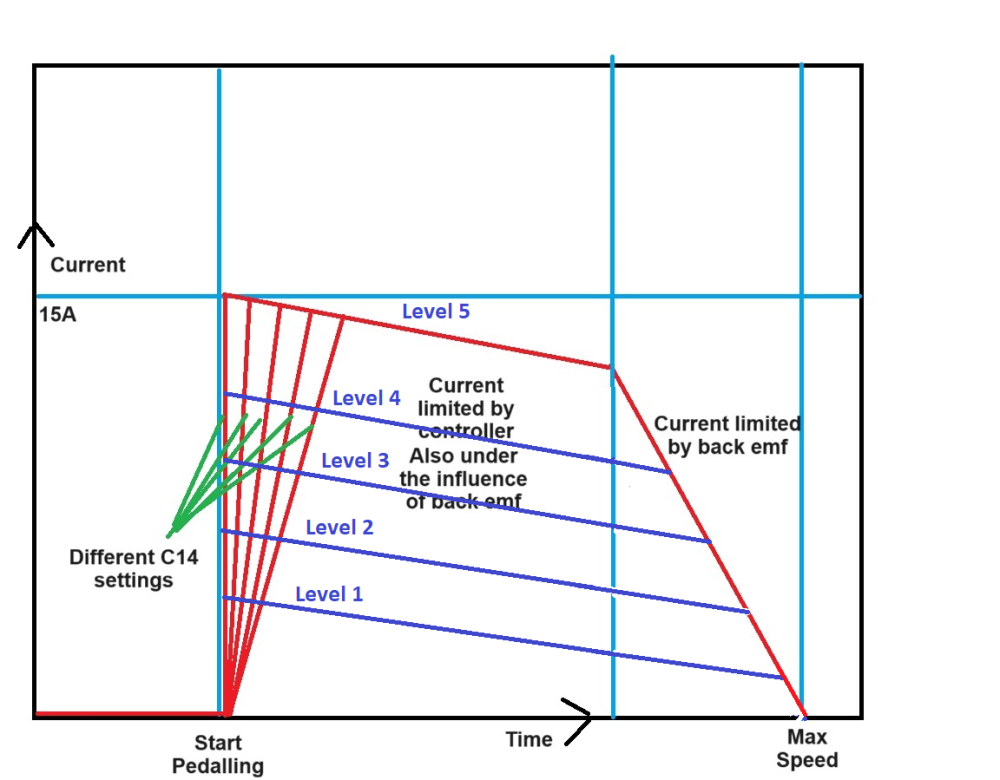
Does the amended graph below represent the lower (blue) power levels better with current eventually being limited by back emf only, due to the controller being unable to supply any more current? I'm not sure why the first red segment (level 5) is sloping. If, in the highest power level 5 , the controller provides 15A (controller maximum), with pulse widths increasing progressively to maintain that value as speed and back emf increase until current is being delivered 100% of the time, should the first red segment not be level rather sloping? I've probably missed something and would appreciate being put right. Once cumulative pulse widths reach 100% of time, rising back emf and falling net voltage cause the steeper red segment because the controller can no longer maintain the current. Since the lower power levels (blue lines) merely represent lower current limits, the controller can maintain them at higher speeds before pulses occupy 100% of the time and the target current can no longer be maintained. Although I have now drawn the blue lines straight rather than kinked, I have kept them parallel to the first red line (level 5), but should they be level or sloping? And why? I appreciate that soft start profiles are superimposed, however it's the ongoing behaviour that interests me rather than the first few seconds. Thanks in advance for any answers.
-
Thanks for the graph. Visual information is always good. I understand the concept of ramping and it's depiction in the graph. When I start off in level 1 or 2, I think can feel the motor ramp up for a couple of seconds (with C14 = 2). It's hard to say if this effect changes when C14 is changed since the change in motor assist strength dominates. To explain this, I've added to the graph to show what I am experiencing (subjectively): Important: The levels shown represent C14 = 2 (default). The differences between levels 1 to 4 are meant to be equal, whereas the differences between level 0 (off) and level 1, and between level 4 and level 5, are meant to be larger. If I select C14 = 1, then levels 1 to 4 move downwards, i.e. they become weaker. Level 5 remains unchanged. The motor feels distinctly weaker than C14 = 2, except in level 5. There is a bigger and very noticeable step up in power between levels 4 and 5. If I select C14 = 3, then levels 1 to 4 move upwards, i.e. they become stronger. Level 5 remains unchanged. The motor feels distinctly stronger than C14 = 2, except in level 5. There is a smaller step up in power between levels 4 and 5. These changes in power are not minor and are experienced throughout a ride, not just when starting off. In level 1, ghost pedalling, the maximum speeds achieved on the same stretch of level road and same wind conditions (i.e. little or none) vary significantly depending on C14 setting. Level 1 is useful in a headwind when C14 = 2, but too feeble when C14 = 1. In the recent strong headwinds along the coast road, which I ride frequently, I've found myself using Levels 1 and 2 (C14 = 2), or levels 2 and 3 (C14 = 1). I've attached a copy of the latest LCD3 manual that I can find (V4.0, 08/10/2022). The description of the C14 settings is: "Assist strength of intelligent pedal motor" (Values: 1 = Weak, 2 = Normal, 3 = Strong). Ramping settings appear in C5 (= 0, 1, 2). I have yet to try these out and have left C5 = 10 throughout. I hope this makes my previous posts a bit clearer. 2022-10-08 KT-LCD3 V4.0 with C15.pdf

-
I've ridden the bike a bit more and, from watching the wattage on the display, it does seem that C14 adjusts the spread, and possibly spacing, of the power levels. For example: In level 1 C14=1 gave around 25-30W and C14=2 gave around 60-80W. Likewise, level 2 gave around 90W and 130W. The readings fluctuate rapidly so it's hard to give definite figures. I haven't yet been able to assess the higher power levels since consistent hills would be needed to keep below the 25kph limit, and there's yet to be any need for levels 4 and 5 anyway. It's possible that all levels change together such that level 5 power varies, or that the spacing of the levels changes such that level 5 always gives full power. I haven't tried C14 = 3, but expect that to be excessively lively. C14 = 1 is may be better for battery life. I couldn't tell if C14 affected ramping as well, as I felt the different amounts of power could be masking this. I obtained an up to date KT manual from the AliExpress supplier and noticed that three previously blank settings in manuals downloaded from the internet (C5 = 0, 1, 2) have now been populated with alternative ramping settings. This must be a recent software change and probably explains what I found with C14, whose function may have been changed at the same time. On the motor noise, I decided to fit wider tyres so, while I had the wheel out, I swapped the motor internals with my spare motor. The noise was similar but more subdued and less objectionable. The motor performance was identical. So I'm thinking that the noise might actually be mechanical noise from the reduction gears, in which case it should reduce as they bed in. EDIT: C14 "Assist strength of motor" I found a long and fairly steep hill this afternoon. With C14 = 1 ("Weak assist strength of motor"), I found that levels 1 to 4 were all lower in power than with the default (C14 = 2), with a big step up to level 5, which gave full power (bike accelerated uphill until it hit the 15.5mph limit). With C14 =2 ("Normal assist strength of motor"), levels 1-4 are stronger and the difference between levels 4 and 5 is less marked. I haven't yet tried C14 = 3 ("Strong assist strength of motor") but it seems reasonable to suppose that levels 1 to 4 would all be stronger still, with a smaller step up to level 5. My feeling from this ride is that KT have actually programmed 7 power levels, mapped as follows: C14 = 1 - ("Weak assist strength of motor") - selected levels 1-4 are mapped to actual levels 1-4. C14 = 2 - ("Normal assist strength of motor") - selected levels 1-4 are mapped to actual levels 2-5. C14 = 3 - ("Strong assist strength of motor") - selected levels 1-4 are mapped to actual levels 3-6. In all 3 cases selected level 5 is mapped to actual level 7 (= full power). This would be relatively easy to implement from a programming point of view and fits the C14 parameter description well. C5 Current limit/Soft start C5 is currently set to 10 (default), which allows the full 17A for which the controller is rated. I'll try playing with C5 = 0,1,2 sometime to explore these (new) soft start settings. C5 = 10 seems quite satisfactory except if pulling away in a higher power setting - perhaps that's where the soft start settings come into their own.
-
I've no idea what the problem might be, but I would check the following (with apologies for stating the obvious) just in case: 1. Is the motor cable plug fully inserted, right up to the line? 2. Is the wheel size set correctly? 3. Is C2 set correctly? My motor runs fine on C2=0, all other settings bar one (C2=2?) made it run roughly or very roughly. Remember to long press the power button to save and exit setting mode. 4. Send a video to Yose so they can see/hear the symptoms. They may send a replacement motor, then you could do a substitution test and see if the problem is with the motor or controller. 5. Don't assume your motor is identical to mine. Take the insides out and count the gear teeth and magnets so you can calculate the reduction ratio and know for a fact what P1 should be - number of magnets x reduction ratio. Taking it apart is easy, undo the collar on the non drive side, remove six Torx screws on the drive side, hold the freehub and lift it out. I held the shaft in a carpenter's vice with hardwood cheeks. To see/count the magnets, undo the drive side collar and six screws, and the end plate and freehub come off as one. One other thought - when I changed P1 to a high value to see what the max no-load speed was, the motor still cut out at 15.8 mph (wheel off the ground). When I spun the cranks really fast the motor hesitated at 15.8mph and then ran up to 18.9mph. I hope this helps but, if not, you need help from someone who knows a lot more than I do, which isn't hard!
-
The torque is fairly strong. Definitely not a weedy motor. The bike maintains 25kph in level 2 in neutral conditions (flat, no wind). I've yet to try it up really steep hills but have noticed the motor feels happier if you keep the speed up by increasing the power level. I've only needed level 3 briefly so far. On the flat, in strong headwinds (15-20mph), and with a bit of pedal input I can maintain 13-14mph in level 2. It's not possible to say whether the "maximum" torque is or isn't 58Nm. The actual torque would depend on the current supplied (my controller limit = 17A) and road speed. Presumably manufacturer's figures are obtained in controlled laboratory conditions. Aikema claim 50Nm for the 95RX on their web site, but it's entirely possible that Yose have had the motor manufactured to a lower speed, and hence higher torque (58Nm), for UK/Europe's 25kph limit. Yose seemed to imply this (in Chinese English...) when I asked the question. The max no-load speed I measured at 18.9mph tends to confirm this, leaving a bit of torque headroom around 15mph so it's got some response if the speed drops on a hill. It's certainly very rideable. For my Yose 250W rear hub motor (OEM version of Aikema 95RX) Yose quoted a reduction ratio of 4.4:1, which suggested P1=88. This figure was clearly incorrect as it resulted in motor cut-off at about 9mph, showing that P1=88 caused the motor rpm and hence actual road speed to be grossly over-estimated. Just trying to clear up this loose end fwiw. On reading other threads it seems that a reduction ratio 4.4:1 might be more typical of a Bafang motor? In which case, Yose may have given me data for an earlier 250W motor sourced from Bafang?
-
Thanks for the suggestions, everybody. Definitely, I'll keep that firmly in mind. That's probably the ideal approach, and it doesn't necessarily have to be a road bike. Before going down that road, I investigated this bike further. Always worth listening to Saneagle The Aikema website gives the following torque, weight and OLD ("installation width") information: 85SXC - 42Nm / 2.0kg / 135mm 95RXC - 50Nm / 2.5kg / 138mm 100SXC - 50Nm / 2.2kg / 142.5 mm The 100SX looks an attractive proposition with significantly more torque than the 85SX for only a small increase in weight, and is significantly lighter than the 95RX, although the installation width is wider. It would also be more transferable to another bike than the 85SX, if the need arose. The drop-outs measure 131.5mm and my spare 95RX motor (without washers) dropped in with at least 1mm to spare. (Presumably the Aikema "installation width" dimensions above include the anti-rotation washers, contrary to the diagrams on their web site.) I bolted the 95RX in position with its anti-rotation washers and I was just able to spring it in. Unfortunately, when I tried adding another thick washer to replicate the 100SX, I struggled to spring the frame apart sufficiently. (It's a extra small frame, so the seat stays are short, which may make the whole back end stiffer.) The 100SX was a good idea, but regrettably not suited to this particular bike. So it comes down to the 85SX. I'd be very happy with a KT 15A controller, and an LCD4 to save space on the drop bars. I think the LCD4 has relatively limited functionality, so would it be wise to buy an LCD3 as well to set up the controller? Yes, a 36V 10-12 Ahr battery should do the job nicely. A 12Ahr battery would make the whole system more transferable to another bike, so a small weight penalty may be acceptable. I'd have to look for a relatively light-weight battery of reasonable quality, and not too expensive. Thinking about minimising weight (from my limited experience), numerous thick 10 gauge (2.6mm) spokes and (presumably) cheap rims seem to make kit motor wheels a good bit heavier than they need to be - not ideal for a road bike. Building a motor wheel with a reasonably decent rim and Sapim spokes would reduce the weight significantly and ride more smoothly. Ideally, I'd like to find find a bare 85SX motor, low speed version. No luck so far... The rear drop-outs are shallow and chamfered at the front, so the anti-rotation washers won't have anything to push against. I'd need to fit two torque arms, but inconvenient mudguard mounting lugs on the back of the dropouts get in the way. I couldn't find a way of fitting torque arms effectively. Sadly, the risk of damage to the drop-outs effectively rules out a rear hub motor. I haven't investigated mid drive motors, as this is an area where I don't know much and would prefer to learn on my own bike rather than someone else's. So I have concluded that my daughter's road bike isn't really suitable for conversion. I'll change her cassette and rear mech so she at least has a 34T bottom gear instead of 28T. She also has an mtb, so I'll have a look at that as a possible alternative for conversion. This reminds me of the old joke about the Irishman who, when asked how to get to Dublin, replied "Well, if I were you I wouldn't start from here". Any further thoughts, anyone? It's really great having this forum. Access to good advice, different points of view, and a sounding board is invaluable. I really appreciate it. In a fairly short time I've gone from knowing very little to feeling reasonably confident about selecting, installing and setting up a hub motor kit, and avoiding at least some of the pitfalls. Thanks again, everybody.
-
Here's how I got on: I set the max speed to 25kph. I tried P1=88 and the bike cut out at around 9 mph. I tried P1=163 and it seemed to cut out just right at about 15 -16 mph, with strong torque at lower speeds. Later, with the wheel off the ground, I found the maximum no-load speed was 15.8 mph. Perfect. (Note: The max speed setting is merely a reference speed and does not affect controller behaviour. The controller calculates actual speed based on P1 and wheel size, and compares the result with the reference max speed. If actual tyre circumference happens to vary significantly from the display/controller's assumed value, then a small adjustment to P1 would compensate for this.) My calculated gear reduction ratio 8.15:1 must be correct. Yose quote 58Nm torque against Aikema's 50 Nm. This seems to confirm that the Yose version of the AKM 250W 95RX is made to their own spec - presumably lower speed and thus more suitable for use in UK/Europe.
-
Unfortunately the forks are alloy.
-
Hi Everybody, I've been looking at a road bike conversion, but this doesn't seem as straightforward as one might think. My daughter has a Trek Lexa road bike, XS frame size. Thinking that it would help her up the steeper hills around Goudhurst in rural Kent, my son-in-law bought her a Swytch front hub kit and asked me to fit it. At first sight the kit looked neat and easy to install... but I soon realised : A 90Whr battery (yes, 90Whr!) would have very little range and is unlikely to deliver enough current to help up steeper hills. Slowing down, the motor would become inefficient and quickly drain the battery. The Trek front drop-outs are 9.5mm and would need filing out to 10mm. The washers for the 10 x 12mm motor axle overlap the lawyers' lips on the forks, which would mean filing the drop-outs 2 - 3mm deeper and reducing tyre clearance. I've advised them to sell the Swytch kit. So, what could I fit? Presumably any front hub motor will have 10 x 12 axle and thus the same installation problems? An obvious choice is a rear hub conversion using, say, Aikema 85SXC as offered by Woosh* with 17Ahr battery. Whilst the battery would fit in the frame triangle, the rear OLD is 130mm and the 95SX and other motors I have seen are 135mm OLD. I'm not keen on stressing the rear triangle that much to make one fit. I will check the OLD again with the wheel out - if it measures 132mm or 133mm it might just work? *It's shown as a "new" product on Woosh's hub motor page but for some reason doesn't appear in the list higher up? The other option is crank drive, either BBS02 or TSDZ2B. I don't have experience of these although I have picked up some insights from this forum. Both have their attractions, but would they make a good conversion on a road bike with XS frame size? Would the BBS02 clear the front wheel? Simple (hub) is reliable... It would be nice if a smaller, lighter battery was available, say 10 - 13Ahr, but I suspect the sizes are much the same (being defined by available bases and cases?) and the weight saving marginal. Perhaps a bag battery under the saddle or in the top of the triangle? Would it be wise to fit wider tyres as part of the conversion? (700c x 25 atm.) Summing up: How can I achieve an installation that will make a nice converted road bike, and still be nice to ride with the battery removed? Is a road bike the wrong starting point? Should we just get an older Orbea Gain instead?! Looking forward to a diversity of views! Cheers, David

-
Update: I'm coming to the conclusion that either: That's just the way it is. The motor seems significantly stronger than it did with the JYT speed controller, which may have had a lower current limit - no way of knowing. (Label on JYT says 15A max, 8A rated, but programmed max current could be lower?) So it would be noisier/harsher due to higher torque, and may get quieter as the gears etc. bed in. I'll try altering C14 =2 (default) to C14=1 and see what happens. (C14=1/2/3 = "Weak/General/Stronger assist strength of motor". Not sure what that means... Perhaps it alters the spread of power levels so that level 1 can be more gentle or stronger ?) Edit: C14=1 felt immediately quieter, however the Watts in the lower power levels was reduced substantially (around 60% reduction in level 1 and 40% in level 2). In higher levels it still sounded a bit rough. At least I know now what C14 does. I may have damaged* a Hall sensor wire? Would that result in the controller defaulting to square wave? (L3=0) If so, presumably it would be a bit harsher/coarser sounding. If it's just running square wave I'll live with it. But how to tell? *With my arthiticky thumbs playing up I struggled to grip the motor lead plug hard enough to push it into the socket. So frustrating. To get it right home I had to wriggle it side to side. Then I found I'd forgotten the rubber end cap and had to unplug it again which was even harder. D'oh! I don't think I would have done any damage as I wasn't holding the cable, but it's always possible. Any other thoughts? I've learnt some useful things from this exercise and feel a lot more confident about configuring the controller. Thanks Saneagle.
-
PS With max speed set to 25kph (P1 =163, i.e. 8.15 x 20), the no-load speed is 15.8mph.
-
Thanks Roger. So that's not an issue in the context above. Good to know.
-
Max. no-load speed, level 5 = 18.9mph = 30.4kph. ( I tried C2 = 0 and C2 = 4 with exactly the same results.) Battery voltage 39.8V (Digital voltmeter. Assumed no significant voltage drop due to negligible current.) Max speed normalised to 36V: 30.4 x 36/39.8 = 27.5 kph or 27,500 m/hr (=17.1mph). Tyre circumference 2165mm or 2.165m. (Measured on garage floor, 1 revolution. +/- 5mm? Marathon Greenguard 700-32 has 3mm latex under tread, hence slightly higher value than 2152mm obtained from tables seems plausible). Wheel rpm = 27,500 / (2.165 x 60) = 212 rpm. (Slightly higher than Yose Power figure 190 - 200 rpm.)
-
PS Any idea what the mystery setting C15 is? Thanks.
-
Interesting. I saw a set of spare idler gears for 95RX on AliExpress yesterday and they were 18/40 teeth, same as mine are. For an older version 95 perhaps? Mine was supplied a year ago. Yose quoted 4.4, consistent with what you have found. I counted the gear teeth, which suggested 8.15*. That gave P1 = 88 (Yose) and 163 (teeth count). When I set P1 to 88 and max speed to 25kph, the motor cut out at about 9 mph. When I changed P1 to 163 the motor started cutting out at 15.5 mph. So I assumed the reduction ratio of 8.15 was about right. (But you know what they say about assumption...) Yose said the motor is wound for 190 - 200 rpm wheel speed. That works out at about 25kph (200 x 2100/1000 x 60), but I know that the motor goes well over that speed when max speed is set high (60kph). It was pulling well at 17mph when I went past 3 cops pretending to pedal hard! 200 rpm @ 4.4:1 = 880 rpm motor speed. 200 rpm @ 8.15:1 = 1,630 rpm motor speed. I have no idea whether either or both figures are plausible! There must be a logical answer but atm it's confusing. * Helical gears - motor 18 teeth, idler 40 teeth. Straight cut gears - casing 66 teeth, idler 18 teeth. I counted them all several times to be sure. So, 40/18 x 66/18 comes out at 8.15:1. What I wasn't sure about was the effect of the idler gear assembly rotating in the opposite direction to the idler gears, but since P1 = 163 worked well I stopped worrying about it. Perhaps idler assembly rotation makes a big difference and Yose was right with 4.4, but then what about P1 = 88 being so far adrift? I might be missing something?
-
Yes, it's a sensored motor. Aikema 95RX. Reduction 8:1 on 700c. The controller KT 17A SVPRD was sold as a sine wave model for which I think Hall sensors are necessary to work properly? If however he motor is working in unsensored mode for any reason, would that mean it is using square wave instead? At lower speeds the pulses are more noticeable but not particularly harsh. The noise/vibration becomes more noticeable as speed picks up (as well as in higher power/current levels). Harder to say about high speed due to wind noise and dodgy hearing, but certainly noticeable at medium speed, say 7-12mph. Restricted to 25kph it pulls strongly until the controller starts tapering off at 15.5mph. Unrestricted, the motor seemed to top out at about 18-19 mph downhill (light load). It felt smoother at these higher speeds, possibly because the current starts tailing off as back emf increases. It "feels" as though it might be using square wave drive or there is a slight timing error. Just that harsh edge instead of smooth whirring.
-
Hi Saneagle (and anyone else), This morning, with maximum speed set to 25kph and P1 set to 163 (as calculated from the gear teeth), motor assistance started tapering off at 15.5mph with watts dropping to around 10 at 16 - 16.5mph. Mostly using level 1 or 2, occasionally 3 if it's particularly steep. Ace! Just one niggle. The motor sounds a bit harsher than it did with the original JYT sine wave speed controller, louder at higher power levels. I can feel the harshness as a buzz of vibration through the pedals and bars at level 3 and above. I can live with it but it doesn't sound like a "right" sort of noise if you know what I mean. I checked the two workable C2 settings and finally settled on C2=0 (default) which seemed marginally smoother. The LCD3 display only offers C2= 0 to 5, whereas the LCD3 manual I found online says C2 can be 0 to 7. The LCD3 display shows a parameter C15, defaulted to 6, for which there is no definition in the manual - could this be relevant? Don't know if it's a safe one to experiment with. The seller describes the KT 36/48V 17A SVPRD controller as "sine wave" rather than "dual mode" so presumably L3 has no effect. I tried L3=0 but no noticeable effect. Is there anything else I could try? Perhaps the motor/reduction gears just need running in? Total so far only about 100 miles including JYT use. Thanks again!
-
After taking a break, The KT controller is installed and running nicely. Thanks everyone for your help.
-
I finally got back to it yesterday, after a long break. Up and running today! Yesterday, I removed the JYT controller from the Yose battery base, removed the circuit board and compound and soldered a 12 AWG silicone lead on to the battery socket with an XT60 connector at the other end. This morning I used the bag Yose supplied with the original kit to house the KT 36/48V 17A controller and connections. I mounted the LCD 3 and KT-V12L PAS sensor, plugged it all together and tidied up the cabling. It was good not having to lose about 3 feet of a 1T4 cable around the battery base and the KT installation looks much neater. being a black bike the cabling isn't too prominent. I changed a few settings and went for a test ride. The Aikema 95RX motor (oem model for Yose) felt a bit harsh. C2 was set to 0 by default, so I experimented and found that C2=4 was smoother. All the other values made horrible noises. I tried P1 = 163 (using my reduction ratio 8.15 based on counting the number of teeth on the reduction gears) and P1=88 (based on the reduction ratio 4.4 supplied by Yose). The bike seemed to go well on 163 but felt sluggish on 88. I left P1 at 100 while I went for a ride and got used to it. During the ride I adjusted the maximum speed from 60kph to 25 kph. This resulted in the assistance tailing off at about 9-10 mph, suggesting that P1 needs to be about 60% higher to avoid the controller thinking the bike is going faster than it really is. So I suspect my value of P1=163 was about right. I'll change it tonight and check by riding tomorrow, perhaps making minor further adjustments as necessary. With the maximum speed set to a high value the bike seemed to fly along, easily holding 16-17mph into a strongish headwind in level 2, and coping with a steep hill in level 3. In level 1 it was easy to ride safely along the sea-front promenade amongst the pedestrians. What a difference the KT controller makes compared to the JYT speed controller! I'm really pleased. A very big thank-you to saneagle for helping me up the learning curve. Next time (Carrera mtb conversion?) I should know what I'm doing! Pic below of the converted bike: My wife's first "proper" bike, "Black the Elder", is a Specialized Sirrus bought cheaply on EBay quite a few years ago. He's had lots of adventures, including a tour in Albania, and now has a new lease of life with lots of tlc and the electric conversion. My wife says all inanimate objects are masculine, hence BtE is a "he". Hmmm.... (Btw, "Black the Younger" was a newer Specialized Diverge (gravel bike), which also did a lot of European touring but fell from favour and went to live elsewhere after I built her a Spa Cycles "Audax" steel road bike with a "Vivaldi" wheelset from DCR Wheels at Lewes. It's the most smooth riding, comfy and generally nice to ride bike she has ever had. He's called "Mr Red". The main problem is she won't let me ride it/him.)

-
PS Apologies for resurrecting an old thread, which I tripped over this morning. Thanks saneagle. I would like to verify my reduction ratio so I can get somewhere near the right P1 value and then adjust in small increments rather than have to hunt over a wide range. But from what you say that may not make a lot of difference anyway. Am I being slightly pedantic?! I'll try Yose's and my values first, hopefully one of them is near he mark.
-
Very interesting and useful post. Although the pragmatic approach to setting P1 seems to work well, I have been puzzling over the need to adjust P1 away from the calculated value by trial and error. So, the system has two ways of calculating speed: For the display speed The display uses the wheel speed sensor to count rpm and applies the wheel size to calculate speed. Being independent of P1 settings there is no scope for casual users to inadvertently mess P1 up, and hence the speed displayed, and then struggle to correct it. At the basic user level the wheel size setting provides a reasonably accurate speed display that is independent of everything else. (The level of accuracy depends on the actual tyre circumference.) For system control/tapering off (P1) The system counts Hall sensor pulses, i.e. number of magnets passing. The P1 setting (magnets x reduction ratio) allows the system to calculate wheel rpm. Not speed. To calculate speed the system needs to know the wheel size. Presumably it must use the same wheel size setting as the display? This is where I get confused The OP reported different speeds for the display and for the system control. However, if the system control uses the same wheel size setting as the display speed, why would the answer be any different? The Hall sensor wheel rpm value should be exactly the same as the wheel speed sensor value, provided that the number of magnets and reduction ratio used to calculate P1 are correct. Perhaps the speeds are in fact the same but the last bit of tailing off is hard to detect, leading to an apparent difference? (The variation in tyre circumference with different widths/profiles will cause errors in speed calculation but this would affect the display speed and system control speed equally and does not seem to account for the variation reported by the OP.) For my Yose rear hub motor (oem version of Aikema 95RX): I am going to upgrade to a KT controller shortly so the P1 setting is of interest. I know there are 20 magnets because I have opened the motor up and counted them. Yose say the reduction ratio is 4.4 and in order to verify this I counted the gear teeth: Inner gear (motor) - 18T, helically cut Idler gear assembly (larger diameter) - 40T, helically cut Idler gear assembly (smaller diameter ) - 18T, straight cut Motor casing - 66T, straight cut (To change the gearing, it is only necessary to change the two helically cut gear sizes.) Reduction motor/idler = 40/18 = 2.22 Reduction idler/casing = 66/18 = 3.67 Overall reduction = 2.22 x 3.67 = 8.15 (> P1 =163) ...but Yose say 4.4 (> P1 = 88). I'll know which is nearer once I have installed and set up the KT controller. Presumably the idler gear assembly rotates inside the casing, at wheel speed or differently? Could this rotation account for the much lower Yose reduction ratio figure? Are my calculations correct or, if not, does anyone know how to calculate the reduction ratio correctly? Yose also say the motor is wound for 190-200 rpm but this is hard to verify without first verifying the reduction ratio. Does anyone know whether a reduction ratio of 4.4 is plausible given the Yose claimed torque of 58Nm, or would a low reduction ratio defeat the object of a relatively high torque motor? I know I can optimise P1 using the trial and error method often recommended but find it hard to understand why this approach should be necessary instead of just setting the "correct" value. If P1 needs significant adjustment, could this be because motor suppliers have provided incorrect reduction gearing data? With differently geared versions of the same motor being available together with bespoke OEM versions, this may possible? Magnet number errors seem less likely but may also be possible. Thoughts, anyone?