sapphire_ad
Members
-
Joined
-
Last visited
Everything posted by sapphire_ad
-
I agree, it will help others I hope, if anybody has more detailed questions what and how to do it, I'm more than happy to help here.
-
Project Complete: Replacing Controller and Display on My E-Bike All done, tested, and the bike is now back on the road! Here’s a summary of what I did from the beginning: Original Setup & Issue My original display (I believe it was a DP24 or DP15) wasn't functioning properly. When plugged into the system (I managed to get software for it), it showed a brief response and the motor turned on, but the display itself remained unresponsive. Initial checks showed that: The battery was healthy and fully charged. The display was receiving correct voltage from the battery. The display plugs were water-damaged, so I replaced them — still no luck. Display Disassembly & Repair Attempt I decided to open the display. Note: It’s mechanically glued shut, so the only way in is by carefully cutting along the edges. Inside, I found a flooded and heavily corroded capacitor. I removed it, cleaned the board, and replaced the capacitor — but the display still didn’t work. At that point, I decided not to waste more time diagnosing the faulty board and opted to switch to a KT controller and display instead. New Setup with KT Controller I ordered a KT controller and display from AliExpress. Once it arrived: I connected the controller to the display and motor. Used WAGO connectors to hook it up to the battery. The display powered up immediately, but the motor didn’t work. I played around with the display settings — the motor started working, but only for a few seconds. Fixing Motor Compatibility Big thanks to [mention=3847]saneagle[/mention] for advice on motor-controller wiring. Based on his suggestion, I cut a spare motor-controller cable in half, stripped the wires, and began testing different combinations of phase and hall sensor wires. Here are the combinations that worked: Phase: Yellow → Blue | Hall: Blue → Green Phase: Yellow → Green | Hall: Yellow → Blue Phase: Blue → Green | Hall: Yellow → Green I settled on the first option. I unsoldered the hall sensor wires on the KT controller and resoldered them accordingly (Blue swapped with Green on hall). The phase wires were soldered poorly to the board, so I cut them near the motherboard and swapped Yellow and Blue externally as unable to undolder from the motherboard Before final soldering, I tested everything again using WAGO connectors — Success! Final Assembly I removed the KT controller from its case and reshaped the case to fit the original Raleigh controller housing. Secured everything in place using resin glue for stability and waterproofing. Also applied clear acrylic to waterproof the motherboard. Reassembled everything, connected it all up — and it works perfectly! Test Ride Results The original 250Wh Raleigh battery isn’t powerful, but it handles flat terrain well. Hill assistance is minimal, but I’m satisfied overall — the bike rides great and feels like new. Notes & Recommendations Lighting: KT controllers don’t support integrated front/rear lights (even one is a struggle for it). I removed mine (and removed cables) and switched to standalone USB-rechargeable lights — better specs and visibility anyway. Patience Required: This project took time, trial and error, and a bit of chaos (especially when my wife pointed out the tools taking over the dining room ). Thanks again to everyone on the forum, especially [mention=3847]saneagle[/mention] for help with motor wiring. Hopefully, this helps someone else tackling a similar project!


-
Hi Stanebike, All soldering is done now! The hall and phase wires gave me a bit of trouble, but thanks to Saneeagle’s advice I found the right combination. I’m reusing the original controller housing, so I had to make a few adjustments to fit the KT controller due to space constraints, but it’s all working fine. I went with a KT controller that includes light control, but honestly, it’s not worth it without a relay—it just doesn’t function properly. In the end, I decided to remove the integrated headlight and taillight and switch to standalone lights instead. I also swapped in a different pedal sensor (bought it along with the KT controller). It works perfectly, though the initial setup was a bit fiddly. Total cost came to about £85 for the kit plus my time—still much cheaper than buying a new display (which is nearly impossible to find anyway, as the German manufacturer confirmed they’ve discontinued it). I’m happy to share the steps I took—just need to document everything properly for the forum before posting it.
-
sorted now just need soldering everything again.
-
I started to swap hall cables initially but no results so started to swap phase cables with no results too, so I used a combinations of both and got the results I wanted i.e. throttle works smoothly and delivers every time when pressed, walk assistance works too with various levels. just wondering now how to connect it all to ensure it is right as need to swap phase connections as well as hall connections. For the last I have plug so can swap around but for phase connectors I would need to solder it again correctly to pcb. Weekend work. Unless anybody has better idea to make it easier (I do not want to leave extra cable that has wago connections all over the place or solder it as risking water leak in a long run. Saneagle, thank you for patience with me, as well as going through the hoops and giving right direction!
-
ok, had a spare cable, 3 thick wires green, blue and yellow, 6 thin cables: white, green, red, black yellow, blue. Are you refering to thick or thin wires here? ok hall sensor would be thin. answered my own question

-
few answers above: 'It still only runs for a few seconds at a time unable to maintain the speed for longer than that. Each time I press the throttle, the battery LEDs light up green.'
-
after pressing for 5 sedonds there is a human figure icon appearing next to speed on display
-
It still only runs for a few seconds at a time. Each time I press the throttle, the battery LEDs light up green. After switching the display off and on, I can press the throttle two or three times, and the motor runs briefly (still very loud), showing an increase in wattage on display. The number in the bottom-right corner (20) starts enters a "thinking" mode at the same time Changing the walk assist level doesn’t affect this behavior, except that the number on the display decreases from 5 to 1 as expected. I have access to controller pcb if need testing (I plan to use existing housing for it as easier to connect to battery)
-
Yes, the motor runs with the wheel in the air (the bike is currently upside down), but it only lasts for 3–4 seconds, the motor is very loud when using the throttle. When riding, the throttle isn't responsive (unless I switch off and on display again and pedal first than press the throttle).
-
212-215W at level 5
-
hi Saneagle, please note that the bike (raleigh evo) doesn't have a separate speed sensor only padal assistance PAS as it was set that way. Does this mean I need a separate speed sensor for it to set it. I have noticed that when I press throttle just after swiching display on it shows the speed up to 20km/h shortly and then throttle stops working. I can do it twice when pressing on throttle and then it is unresponsive unless I switch the display again
-
the led is blinking red on/off when pedalling. let me adjust C1 and P2 and also check on the magnet (it is on the LH as per installation guide) Saneagle - I will try to test it without PAS too
-
P4 = "zero startup" C4= " zero starup" speed 20km/h speed sensor hall; speed on lcd - need to records as difficult to test and wach everything
-
I reviewed the manual and reset all parameters, now I get throttle to work at start and occassional when pedalling all is as follows: P1=87 P2=0 P3=0 P4=0 P5=7 C1/C2=0 C3=8 C4=2 C5=7 C6=3 C7/C8/C9 =0 C10 =n C11=0 C12=4 C13=0 C14=2 C15=6 but throttles only works for a while and then stops, no other assistance is happening? I also notice that motor is quite lound and wonder about C2 to swich to 2 or 4 formotor phase but not sure whether it would make any difference.
-
pass as per photo, no break sensor fitted

-
So I have now changed some settings but motor is not working at all now. 1T4 included. This is what I have: wheel set at 20"; speed at 72km/h P1 =87 P2 =1 P3=1 P4 =0 P5=7 C1 =0 C2 =0 C3=5 C4=4 C4=4 50 C5=10 C6=3 C7=1 C8=0 C9 =0 C10= n C11 =0 C12=4 C13=0 C14=2 C15 =6
-
I recently replaced the controller and display on my Raleigh Evo with a KT setup. The components I’m using are: KT Controller 36/48V SVPR 7A KT LCD3 Display KT PAS sensor KT Throttle Everything is connected and powers up fine, but I’m seeing some strange behavior, and I’m not sure if it's due to motor configuration or something else. Here’s what’s happening: When I first connect the battery and turn on the display, pressing the throttle works briefly — the motor spins for a few seconds — but then stops responding. If I pedal with the PAS level set to 5, the motor kicks in as expected and runs with me pedalling at the same timie. However, once I stop pedaling, the assistance also stops — and when I start pedaling again, PAS no longer activates. The throttle remains unresponsive all the way. Note battery is showing as full on the display and actually it is full. Has anyone experienced similar issues? Could this be a settings/config issue in the LCD3, or something else entirely? I have set my wheel to 20" but not sure on P1 etc. and C1 etc. I have set as follows: P1=87 P2=1 P3=0 (throttle and pass independently) P4=1 (throttle when pedalling) P5 = 7 (36v / 250Wh = just under 7Ah) But completely have no idea on C values Any advice or insight would be appreciated! Thanks!
-
all parts arrived now, I will show when all done, as planning to use existing controller box for new controller, it will fit well and can connect to battery as well.
-
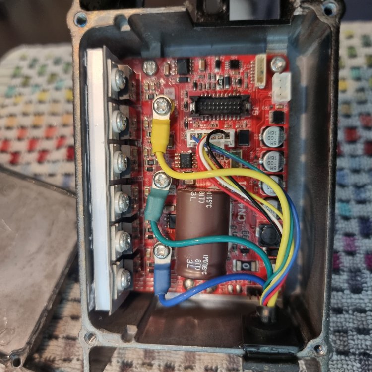
Quick update – new capacitor is in place and everything's been tested. The battery is giving between 5–6V on the board, but unfortunately, the board itself is completely unresponsive – no signs of life at all. To really figure out what’s wrong, I’d have to test each component individually, and frankly, at an estimated £50/hour for the effort, it’s probably not worth it. So, back to the recommendation from Saneagle – going the KT controller and display route. I'm leaning toward the KT LCD3 with the matching sinewave controller (36V, 15A). I’ll need to factor in a pedal sensor, speed sensor, and throttle too, which I hadn’t originally planned on. Any advice on the specific KT setup would be appreciated. Also, does anyone know if the KT controller could fit in the existing controller housing? I’d rather not mess with the battery fittings unless someone has a good alternative suggestion. For what it’s worth, the battery passed all tests just fine. I'm unsure how to handle the connection to the 4-pin setup without the original housing – or where I could place a new controller box if I leave the existing one just to keep the battery mount intact. Thanks for any tips or ideas!

-
I thought about it too. Just cleaned the board and bought new capacitor as the one in there was all gone. I will update as soon as soldered, agree that no harm in doing so.
-
Ok, I think the case can be closed because the display is flooded. All other connecions where just fine and display not really responsive, I took a hit and opened it (heat gun and sharp blade - no other metod) and capacitor flooded and motherboard too on one side. Sound like I'm looking for alternative option for display and controller (back to square one ) . Unless anybody from the forum think of an alternative still


-
ok it make sense with wiping code in the CPU. when pressing LCD it remains completly blank no response.
-
After some testing, here’s where I’m at: All cables from the controller up to the display plug have continuity The battery is reading 41.2V after a full charge When the battery is connected, the display plug shows 41V–40.8V depending on pin combinations — but I’m seeing +/-40V between one pin and any other pin, which seems odd. Not sure if this is expected behavior? Given this, I’m starting to think the display might be the issue, not the controller. Unfortunately, I don’t have another compatible display to test with. At this point I’m considering switching to a KT controller with LCD5, which might end up cheaper and faster than trying to hunt down a DP16 or DP27 display. For context: The German manufacturer confirmed those displays are no longer in production Raleigh support claims availability might return by end of December 2025, which is… not helpful Looking for advice: Can I reuse my current motor and battery (36V geared hub, 250W, 12-magnet PAS sensor) with a KT controller setup? Should I reuse existing cabling, or is it safer to replace it all when switching to KT? Anyone tried opening one of these glued dp16/dp27 displays? The manufacturer said it can be done using heatgunand sharp tools, but there’s no guarantee it won’t break. It’s turning into a bit of a nightmare, so any tips or shared experience would be massively appreciated!
-
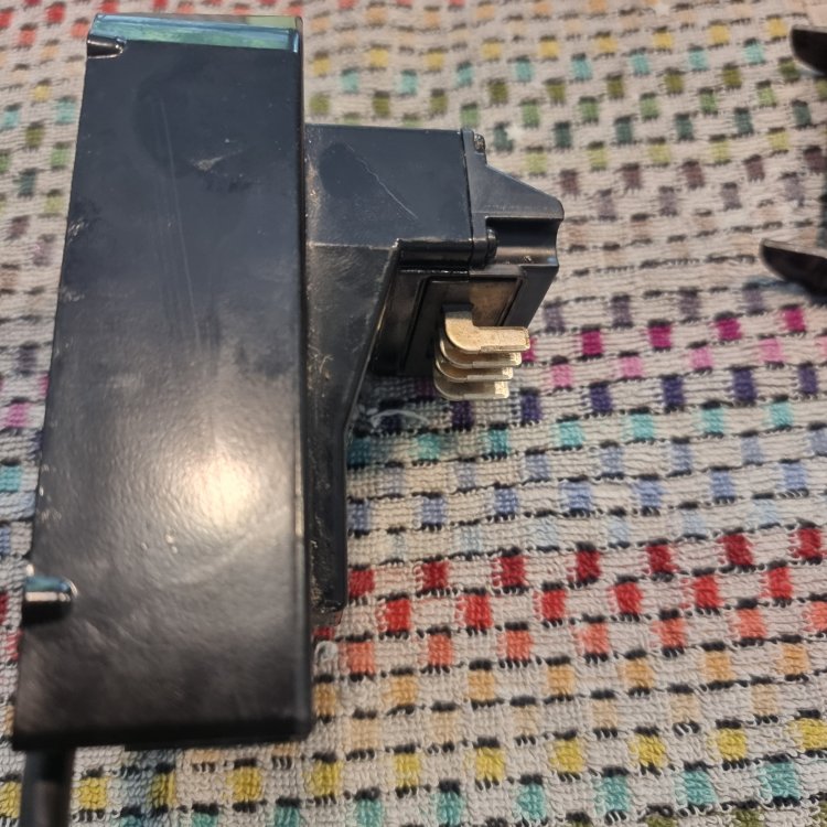
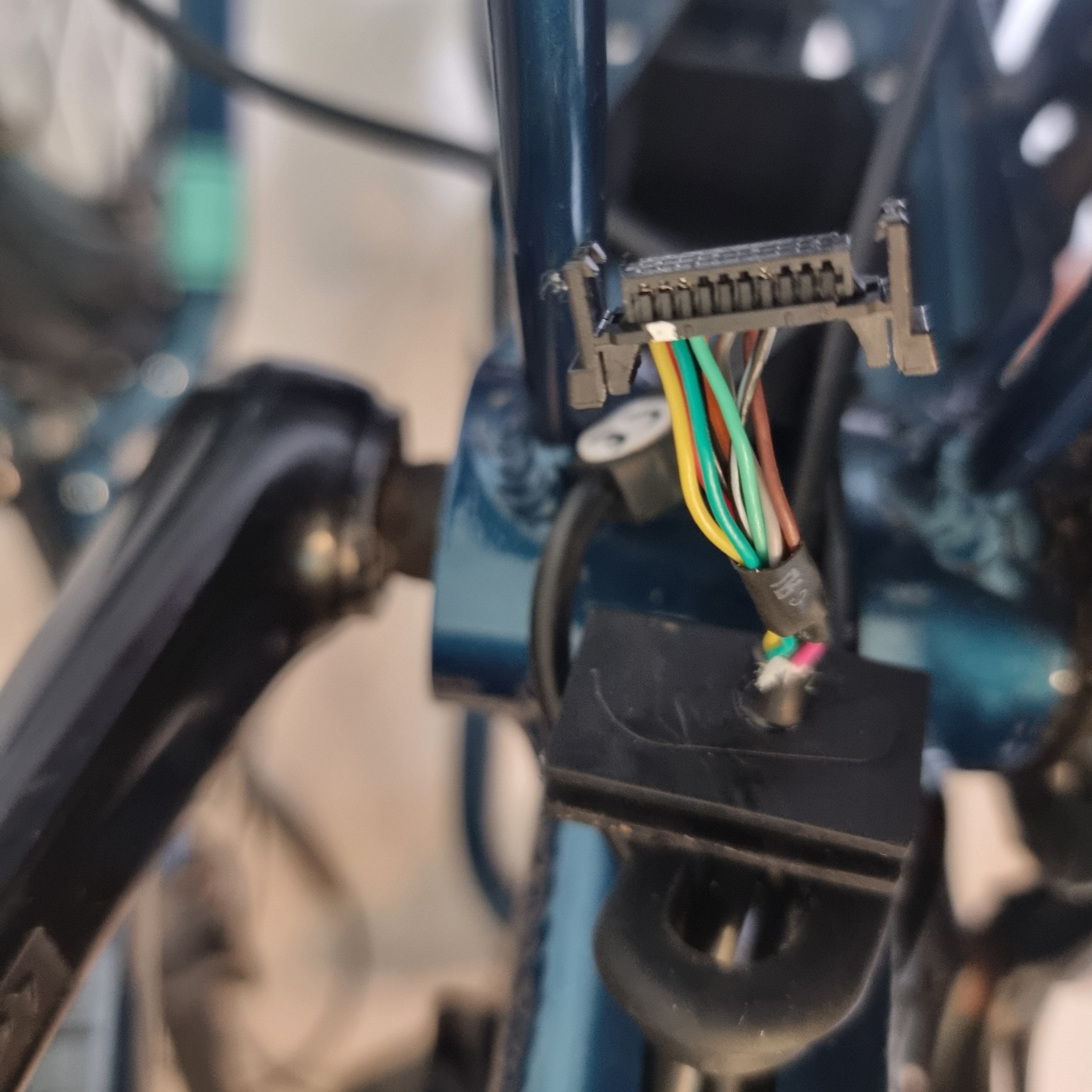
Hi all, I’m troubleshooting my Raleigh EVO electric bike, specifically the controller (motherboard). I’ve disconnected the components and need to test whether the controller is still functional, as I’m not getting power to the display. Here’s what I’ve done so far and what I need help with: The battery is fully charged and functional (tested it brings 40v) I’ve disconnected the cables going from the motherboardto: Display (5-pin: Red, Blue, Green, Yellow, Black — black is center pin) Lights (2-pin: White and Brown) PAS sensor (3-pin: Orange, Pink, Purple) [*]Earlier, the display powered up when connected via USB to my laptop, but not when plugged into the controller. [*]I found that the original plugs between display and controller were flooded/damaged, so I’ve replaced them and soldered new connections. [*]Now, no power seems to come from the controller to the display, so I need to test voltages and check if the controller is dead or salvageable or some issue with cables. I tested continuity across the cables between motherboard plug and display plug and these are fine (after my soldering), but I’d like to know how to test and what to expect re. voltages if any: Display (5-pin plug): Red, Blue, Green, Yellow, Black I believe Red = +5V and Black = GND, but what about the others? Should I see 5V between Red and Black when the battery is connected? how to test separately display cable with no connection to battery - it is glued so no way to open it (unless I'm lucky to get it apart but would like to avoid it as a start) [*]PAS Sensor (3-pin): Orange (links to 3 cables on the motherboard end - potentially ground), Pink, Purple What voltages or signals should I see while turning the crank? Is one of these a 5V supply and the other a pulse signal? how to thest PAS sensor itself without turning the crank [*]Motherboard - how to test it? I have tested continuity against plug for motor but it looks like one end links to all on motherboar I assume due to multiple connections. Is there a safe way to test the controller output with the battery connected? Since the battery is 36V, I’m cautious about damaging anything or shorting components. I have attached few photos. Any advice on expected voltages, safe testing methods, or tips for diagnosing a dead controller would be much appreciated! Thanks in advance!