Gavb
Members
-
Joined
-
Last visited
-
I would just like to say thanks to all who offered their advice. My bike is back up and running and I have happily commuted to work and back with no problems. I have learnt a lot in only a few days. Many thanks again.
-
No it is not the brake. disconnected the brake cable so no contact with rims. Def. coming from hub motor
-
I just made a new shunt out of longer and slightly thinner wire and I have got slightly different readings between the 3 good combinations now. Readings were between 0.72 and 0.80mv for one combo and the other 2 were flicking up and down from 0.75 to 0.90. I have gone with lowest option. Thank you so much for all of your help. I have my bike back up and running! My only concern now is that I have done something to my hub motor as when it comes to a halt it has started squeaking for the last few slow rotations. When i push my bike forward the motor is also slightly squeaking.
-
Great news! Made the shunt connected up my multimeter and got some readings. 3 were initially much higher (5.0+ mv) then setttled down. These were the false positives that you mentioned I think The other 3 readings were all very similar. Full throttle initially and all went up to 1.8mv initially and all settled to flicking between 0.13/14mv. So how do I choose which one of the 3 if they are all measuring about the same?
-
By the way, it was mentioned somewhere that there will be 3 out of 36 possible combinations that will result in forward movement. I have 6 working combinations all spinning forwards. Other combinations span forward too but made interesting noises. 6 were all ok but some made the wheel spin much faster than others. Is that normal? Do I need to test the current of all 6?
-
Thank you. I will make the shunt tomorrow and let you know how I get on.
-
Ok great. I have a newish bosch iron that does not work so will use 100mm from one of the wires from the lead (would that be 2.5mm?) or I have an old extension lead cable. Don't really want to have to go out and buy a big reel of 2.5mm twin and earth. I will use the croc leads to connect to the probes.
-
brilliant. last 2 questions (I hope) 1. Where is best place to get the 14g wire and 2. What wire do i need for leads to probes? Can I use croc clip test leads and just cut crocs off one end and solder to ends of 14g. I can then clip crocs onto probes?

-
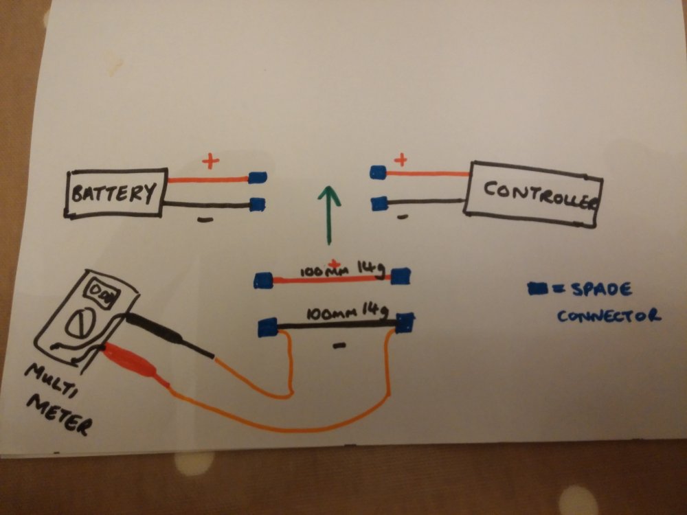
Ok, I am learning slowly. Thank you so much for your help and patience. Does this diagram look right?
-
Can I leave the + wire connected as normal and just use 100mm 14g wire with 2 spade connectors at each end to connect into my - wire, and solder in two smaller wires to the spade connectors to connect the probes to? I don't understand why I need the red thick wire too.
-
I don't know where the 3 smaller wires are going and how this shunt would connect into the black -ive wire.
-
To be honest I don't know how to make the shunt! I have looked at you picture of yours (on the paper plate) and don't understand what the wires are for. I can see 3 small ones and 2 larger ones (black and red). I am really clueless. Sorry
-
Just bought one of these as I thought I could just connect it and it would measure current!! I really dont know what I am doing do I http://www.amazon.co.uk/gp/product/B000JQ4O2U/ref=oh_aui_detailpage_o00_s00?ie=UTF8&psc=1
-
Apologies, I am still finding my way around how to use this site and I think I have started a conversation as well as replying here. I have tried to have a look at your instructions about how to measure the current and although I feel that I am quite a practical person, I am unsure how to connect it up and am a bit lost to be honest! As I was saying, I have tried 36 combinations of hall and phase wires and have found a few that work but the next step I have been told to do is to choose the one with the lowest no load current draw. I don't even know what that means! The company who sold me the controller wont help me any further. I think I have got myself in too deep with replacing my controller and am really unsure what to do next. Is there anyway that you could send me a diagram of what wires I need to connect to where etc and I will have a good go at this. I tried looking at your photos but cant work out what wires go where. I had no idea that I was going to have to get this technical. I freally want to learn though! I bought an ebike kit before so everything was just plug in and go! I think I need to put the shunt in between the battery and the controller on the black (-ive, black) wire. Is that right? battery ________+(red)_____ controller ______ motor battery________-(black)____ shunt _____ controller ______ motor So sorry to trouble you, I bet you are regretting replying to my post. Everyone is busy and if you don't have time to provide this much support then that is fine! Thanks again, Gavin.
-
Thank you for the information but I am really new to electrics. I have already bought a multimeter and was hoping I would be able to connect the prongs to some of the wires and get a reading. I'll have a good read of your information again later when i have more time.