KU63 controller circuit board connections

eHomer

Esteemed Pedelecer
Aug 20, 2012
635
164
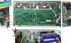
I'm trying to figure out some of the external lead connections on what I believe is a KU63 controller.

When I upgraded one of my bikes to a BMS sinewave controller last Summer, I cut the leads off the original square wave KU controller. I know it sounds stupid now, but the reason was that the original controller had a very neat loom and waterproof connectors, carrying the throttle, control panel, brakes, and lighting to the front in one thin cable. I converted that for use with the new sinewave controller, and it turned out very neat.

Because of the original non standard loom, some of the board connections are not the standard groups and colours that I guess the KU63 normally had. There's no sets of black/red/green for the throttle and PAS for instance.

I'm now trying to put the connections back on it, so that I can use it as a spare/test controller.

The Motor phases, hall wires, and main red/black power are still connected ok, but I'm trying to work out the other connections for the 3 PAS level control panel, the standard throttle, and PAS sensor.

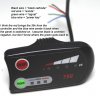
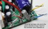
The PAS control panel cable has red, black, green and blue.
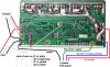
I think the red is the red wire next to the main red in the controller, bringing the full 36v positive to the controller,
I think the black is a common negative,
I think the blue feeds the 36v back to the controller when the panel is switched on.
I don't know where the green "signal" wires connects to back in the controller (there's no vacant green wire in there).

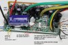
I'm guessing that the throttle and PAS sensor connect to the red and black at the right hand end, and the signals come back on the yellow and orange.

That leaves the three white wires, which presumably are the speed restricter and the brake cut off ?

What I've searched for on the web is a picture of the circuit board layout with the connections marked, but I've only found circuit diagrams instead.

3 speed pas panel.jpgku end connections.jpgku front connections.jpg
 

eHomer

Esteemed Pedelecer
Aug 20, 2012
635
164
Thanks for the reply John.

I had found that web page with my Google search, and found it to be the most informative so far on the KU63.

So may photos and diagrams, and the chap had even explained all the mods possible.

Unfortunately though, none of the photos showed clearly where the wires were connected on the board, and the diagrams were all circuit diagrams, with no circuit board layouts.

I tried to trace the connections from the circuit diagram, but couldn't make any sense of where the external connections were made, or their wire colour.

Funny thing too, the wires that were visible were different colours to mine.
 
D

Deleted member 4366

Guest
It's a KU65 not a KU63.

I can figure out some of them without opening mine. If we can't figure it out between us, I'll open it.

Last photo:
Blue is return 36v from panel
The white wire next to the black one is the speed limiter ground. The other two will be its partner and the throttle signal.
The Yellow one is most likely the brake signal. Its partner will be a black ground
The red wire near where the battery comes in will be the 36v to the panel.
The red wire at the other end is a 5v for throttle or PAS. If the orange one is joined to it on the PCB, it'll be the PAS 5v.
The thin blacks are all common grounds.There should be three: PAS, throttle and panel.

This means you're missing two wires, the green signal from the panel, and the green signal from the PAS.
 

john h

Esteemed Pedelecer
Nov 22, 2012
510
147
murthly castle estate
I used to have the all the ku diagrams on my other computer, i would download from B M S, all i have now at this time are the ku 123 high speed+ ku 66 torque controlers as i have these for a project to come. endless sphere have stuff on controlers,
 
D

Deleted member 4366

Guest
The pad between where the orange and white wires are soldered is also an input to the CPU. Does it look like it had a wire on it?
 
D

Deleted member 4366

Guest
Curiosity beat me. I had to open it. Unfortunately it's wired differently. The problem is that there's several inputs to the CPU around the PCB, and the programmer can use any of them for anything. The only one that's fixed is the brake wire. Which must be the white nearest us in the photo. The two pads are SH and SL for high and low brake signals. Normally the brake yellow (signal) is on SL, but your white seems to be on SH, so I guess its partner was a 5v wire. I think I've figured something though. I think your signal wires are all white instead of green. Is the one next to the common grounds on a joined pad or on one marked SD. SD is my throttle. My PAS is in the middle of the PCB marked ZL, which is where the other white appears to be. My panel signal goes to 3, which is the last pad next to where your yellow is, so yellow is probably panel signal.

That's everything covered then.

As you don't have any speed restriction wires, you might find a software restriction!
 

eHomer

Esteemed Pedelecer
Aug 20, 2012
635
164
John, thanks for the pointer on where I might find some KU diagrams.


Dave, thanks for all the effort you've put into checking your own controllers.

I'll work carefully through your comments with a magnifying glass and meter on my controller board, then report back on here with whether I've got it going or not.
 

eHomer

Esteemed Pedelecer
Aug 20, 2012
635
164
I'm very much obliged with your help on this.

I've now worked through your replies and I think you've sorted it for me.

I've taken a photo of the back of the circuit board and shown the front connections as insets around the edges of it.

I should mention that the original loom was a complete sealed unit, which commoned many of the wires in a single cable to reduce the clutter running to the front of the bike for the panel, throttle, and brakes.

The controller therefore only had four cables coming out of it:

An eight way to the motor,
A two way to the battery,
A two way to the PAS sensor (because it was nearer)
and a multi way to the handlebars carrying everything else.

So I would guess that last multiway had all the negatives in one black wire soldered to the board and all the 5v feeds in one red wire.

As you deduced, I think the brake must have been connected to SH, and that the two microswitches were then connected to the common 5v within the loom.

You must also be right with the PAS and throttle signals being white instead of green. The SD pad between the 5v reds and the negative blacks is seperate, with just the white stub on it, so I'll take that as the throttle signal return.

Yes, ZL had a white stub on it, so I'll connect that to the PAS return signal.

As you say, that left just the PAS control level return signal, which I'll connect to ZF, where the yellow stub was. The colour probably changed from the green wire within the loom connections.

I shan't bother with the brake connection on SH at the moment, as it's just for testing.

I'll get cracking with the soldering iron and report back after testing.

I must say, the quality of workmanship on these circuit boards varies widely. As you can see from the photos, the original soldering on this KU65 is quite scruffy, whereas those Conhismotor controllers were beautifully soldered, (even though neither of them worked though ! :rolleyes: )

connections.jpgnew connections.jpg
 
Last edited:
D

Deleted member 4366

Guest
The brake will work on SL. If you use a switch,the other wire will be a common ground. If you use an in-line hall sensor or similar, the signal goes to SL and the other two are 5v and 0v.

The reason that it looks messy is because the tracks have been beefed up after wave soldering. The wave soldering only puts a thin layer of solder on, which is not sufficient to carry the current, so it can heat up and melt off to cause all sorts of damage. They therefore drizzle extra solder on the high-current tracks to reduce the resistance, sometimes reinforcing with a strand of plain wire. Sometimes they don't do it on these KU series controllers, so it's advisable to do it yourself, especially on the KU123 with 30 amps.

It's a lottery whether they do it or not. I have a KU63 and KU65 in front of me. Neither have been done, but they should be OK at 15 amps. The thicker reinforced tracks would mean less heat, so higher efficiency, so whenever you open one, you should beef them up if not already done, but double check for whiskers and bridges afterwards.
 

eHomer

Esteemed Pedelecer
Aug 20, 2012
635
164
They're beefed up already Dave, with wire and solder, just as you say.

I've got it back together now and just tried it.

No bangs or smoke ( :rolleyes: ), and the panel lights up an the buttons and leds works ok.

I can't get it to spin the motor yet though.

I'd forgotten that when it was last fitted to the bike that the throttle wouldn't work without the pas turning first, so I'll have to rig something up to test that. ( I'm not dexterous enough to flick the magnet rapidly past the sensor and turn the twist grip at the same time !)

Is there a mod that can be done to the KU65, so that throttle can be used from standstill, and yet still enable pas if switched on ?
 
  • Like
Reactions: Jasong
D

Deleted member 4366

Guest
There was a "PAS start" version of the KU63, which had a jumper wire on the back of the pcb. If you cut the jumper, it reverted to normal throttle operation. Yours doesn't have the jumper, so I guess you're pollacksed.
 

eHomer

Esteemed Pedelecer
Aug 20, 2012
635
164
Success !

I connected the PAS sensor and flicked the magnet past it a few times and the motor started ok, then the throttle kept it going, so it's working fine now.

Thanks for the help identifying the external lead connection points Dave.

I can live with the PAS start, it's mainly going to be used for testing. :)
 

eHomer

Esteemed Pedelecer
Aug 20, 2012
635
164
I've resurrected this thread because I've now pressed this "spare" KU65 controller into use on my Dahon Boardwalk with the Q100 36v 250w 290rpm motor.

I've now discovered that although it appeared to work, it doesn't seem to be switching the three different levels of PAS. All I get is one level, which I think is level 3.

Thinking about what has been posted on this forum before, I understand that the green wire back from the 790 led controller panel gives 1, 2 or 3v back to switch the levels of PAS.

If so, then maybe my rewire is just feeding a higher voltage back, regardless of what the panel is showing (the leds do step through the three settings when the pas button is pushed).

Looking back at the board photos that I posted earlier on this thread, I've got it on ZF. I'll dismantle it all tomorrow and have a look to see if the solder blob is maybe shorting against the adjacent tags, Q and A3.
 

eHomer

Esteemed Pedelecer
Aug 20, 2012
635
164
Thanks Dave, I'll take the board out of the controller tomorrow and check the connections.

I'm pretty sure the three speed switch (signal) wire from the 790 panel is connected to ZF, but I'm I'll check that it has no solder whiskers around it.
 
D

Deleted member 4366

Guest
That's wrong then. It should be ZL. ZF is for the three-speed switch on the KU 63 and KU123. It's not connected on the KU65.
 

eHomer

Esteemed Pedelecer
Aug 20, 2012
635
164
That's wrong then. It should be ZL. ZF is for the three-speed switch on the KU 63 and KU123. It's not connected on the KU65.
I've managed to confuse myself again Dave, (not a new sensation, admittedly).

Looking at the (very useful) table of connections you posted, I was taking "ZL - PAS signal" as the connection back from the PAS pedal sensor, which is what I've got it connected to.

If ZL should be connected to the PAS level signal coming back from the 790 LED panel, then what should the PAS pedal signal wire be connected to ?
 
D

Deleted member 4366

Guest
PAS signal should be connected to ZL. There's a couple of unmarked pads in a\ row next to ZL, which is where the three-speed switch goes.