Help! 2 wheels better than 4, when its not raining.

bob d

Finding my (electric) wheels
Oct 14, 2023
21
0
Hi again and the readings from the resistor are 37V at one end and 0.3 at the other end. I've taken this measurement between the main black wire going into the PCB (which I believe is called ground) and each end of the resistor. However I don't know what the readings should be.
Thanks Again
bobd
 

saneagle

Esteemed Pedelecer
Oct 10, 2010
4,181
2,077
Telford
Hi again and the readings from the resistor are 37V at one end and 0.3 at the other end. I've taken this measurement between the main black wire going into the PCB (which I believe is called ground) and each end of the resistor. However I don't know what the readings should be.
Thanks Again
bobd
It shouldn't be as low as 0.3v. I can't remember what a normal value is - possibly around 24v. Something downstream must be shorted to ground. The 5v regulator is the most logical culprit, so you could simply remove it first, then check the resistor again.
 

bob d

Finding my (electric) wheels
Oct 14, 2023
21
0
Arghhhh, remove that little 3 legged black thing indeed. Well that certainly will test me, but best foot forward etc etc.
That'll be a job for tomorrow, and a steady hand and perhaps a third hand form a friend.
Oh yes I forgot to mention, the outer painted type of layer on the resistor has all crumbled away in bits, perhaps due to overheating.
Watch this space as they say and I'll report back to you accordingly.
Many Thanks again

bobd
 

saneagle

Esteemed Pedelecer
Oct 10, 2010
4,181
2,077
Telford
Arghhhh, remove that little 3 legged black thing indeed. Well that certainly will test me, but best foot forward etc etc.
That'll be a job for tomorrow, and a steady hand and perhaps a third hand form a friend.
Oh yes I forgot to mention, the outer painted type of layer on the resistor has all crumbled away in bits, perhaps due to overheating.
Watch this space as they say and I'll report back to you accordingly.
Many Thanks again

bobd
You just melt the solder on the back side while pulling a leg up with a cocktail stick or whatever you can lever it up with until all three are clear. If you need to put a new one in and the holes are blocked, put your soldering iron on the back of the pad to melt the solder, purse your lips and bring it close, then do a "pah" to blow it clear, or you can use a solder sucker or wick, which is harder.

Learning by doing - the best way to lean stuff!
 

bob d

Finding my (electric) wheels
Oct 14, 2023
21
0
Well I'm back and no burnt fingers etc and the little black 3 legged thingy is out. The holes are clear and any solder splatter which got on the PCB has been delicately removed.
Unfortunately the readings are still the same. I get 37V at one end of the resistor and at the other end 0.3V and one reading of 0.6V, and just to check to make sure I'm using the multimeter correctly I'm connecting the black probe from the meter to where the black battery wire is soldered into the PCB and the red probe from the meter to either end of the resistor.
So I'm now wondering what is next to investigate ?
Many Thanks again
bobd
 

saneagle

Esteemed Pedelecer
Oct 10, 2010
4,181
2,077
Telford
Well I'm back and no burnt fingers etc and the little black 3 legged thingy is out. The holes are clear and any solder splatter which got on the PCB has been delicately removed.
Unfortunately the readings are still the same. I get 37V at one end of the resistor and at the other end 0.3V and one reading of 0.6V, and just to check to make sure I'm using the multimeter correctly I'm connecting the black probe from the meter to where the black battery wire is soldered into the PCB and the red probe from the meter to either end of the resistor.
So I'm now wondering what is next to investigate ?
Many Thanks again
bobd
We're making progress. just need to go a bit further. Measure the resistance of that big resistor. it should be in the region of 180 ohms. If it's wildly off that, it could be blown. If it's OK. I guess you have to lift the 12v regulator, otherwise replace the resistor first. The schematic is shown at top left of the image in the link below. There might be some minor differences, but nearly all Chinese controllers work like that. Yours won't have the two switches indicated.
 

bob d

Finding my (electric) wheels
Oct 14, 2023
21
0
Ah, right, yes, in other words I aren't exactly full of confidence with the old multimeter, but after a chat with a mate who is I've done the recommended stuff and checked the resistor (the one next to the 12V rgulator) and the reading just stays at 0.0.
I've had the multimeter dial set at its lowest position and at 2k and also used a different multimeter and still nothing.
Also said mate suggested removing one end of the resistor from the PCB and re checking and still there is no reading.
So, as I haven't got any odd resistors laying around I cant think of anything to make a comparison test on and confirm what I'm doing is correct. If I knew what spec a replacement resistor was I'd order some from Amazon as they seem to have various types.
So, I'll await your advice and proceed accordingly.
My grateful thanks again

bobd
 

saneagle

Esteemed Pedelecer
Oct 10, 2010
4,181
2,077
Telford
Ah, right, yes, in other words I aren't exactly full of confidence with the old multimeter, but after a chat with a mate who is I've done the recommended stuff and checked the resistor (the one next to the 12V rgulator) and the reading just stays at 0.0.
I've had the multimeter dial set at its lowest position and at 2k and also used a different multimeter and still nothing.
Also said mate suggested removing one end of the resistor from the PCB and re checking and still there is no reading.
So, as I haven't got any odd resistors laying around I cant think of anything to make a comparison test on and confirm what I'm doing is correct. If I knew what spec a replacement resistor was I'd order some from Amazon as they seem to have various types.
So, I'll await your advice and proceed accordingly.
My grateful thanks again

bobd
I'm pretty sure that the value isn't critical, but you do need a rating of at least 2w because it gets hot. If you get one around 180 -200 Ohms, it should be OK. Get a 5v regulator while you're at it because it might well be blown. See if you can get the designation off it then use Google for its data sheet. the only important things are its current rating (probably 100ma) and which way round the legs are. Ground is always in the middle, but the in and out can be either way round. It's a shame we don't have Maplin anymore. You can find these things on Ebay, but the postage bumps the price up for single items.

Search "5v Regulator TO-92" and "2w 200Ohm resistor"
 

bob d

Finding my (electric) wheels
Oct 14, 2023
21
0
Right, here we go with my findings.
THE REGULATORS
As you said regarding price it seems that from ebay + the P&P which is about as much as the components the price gets bumped up. On amazon (with prime) they are double the price to those on ebay, but there is no postage, plus I can easily send them back if not suitable, unfortunately they will take about a week to get here.
So, what I've found on 4 different regulators of the 5V TO-92 type, is that the ground is always the middle terminal and the output is to the left, that's when your looking at the flat face of the regulator and it is stood on its three legs. However I don't know which way around the legs on the regulator from my PCB are.
All of the 5V output regulators I have looked at have a maximum input voltage of 30V.
The title of the regulator I have ordered from Amazon is
Chanzon 50pcs 78L05 TO-92 Three-Terminal Voltage Regulator Stabilizer Transistor
There is a data sheet on amazon when your looking at the component of which I've attached a copy (I think).

THE RESISTORS
The resistors are also from amazon and have the title:
sourcing map 50Pcs 200 Ohm Resistor, 2W 5% Tolerance Carbon Film Resistors, 4 Bands for DIY Electronic Projects and Experiments

I have ordered the above and hope I have it correct, but if not please re educate me and I will re-order accordingly.
In both cases it seems as though I will get a small sack full and so if you know anyone who wants the left overs they're welcome to have them.

Many Thanks again

bobd
 

Attachments

saneagle

Esteemed Pedelecer
Oct 10, 2010
4,181
2,077
Telford
I'
Right, here we go with my findings.
THE REGULATORS
As you said regarding price it seems that from ebay + the P&P which is about as much as the components the price gets bumped up. On amazon (with prime) they are double the price to those on ebay, but there is no postage, plus I can easily send them back if not suitable, unfortunately they will take about a week to get here.
So, what I've found on 4 different regulators of the 5V TO-92 type, is that the ground is always the middle terminal and the output is to the left, that's when your looking at the flat face of the regulator and it is stood on its three legs. However I don't know which way around the legs on the regulator from my PCB are.
All of the 5V output regulators I have looked at have a maximum input voltage of 30V.
The title of the regulator I have ordered from Amazon is
Chanzon 50pcs 78L05 TO-92 Three-Terminal Voltage Regulator Stabilizer Transistor
There is a data sheet on amazon when your looking at the component of which I've attached a copy (I think).

THE RESISTORS
The resistors are also from amazon and have the title:
sourcing map 50Pcs 200 Ohm Resistor, 2W 5% Tolerance Carbon Film Resistors, 4 Bands for DIY Electronic Projects and Experiments

I have ordered the above and hope I have it correct, but if not please re educate me and I will re-order accordingly.
In both cases it seems as though I will get a small sack full and so if you know anyone who wants the left overs they're welcome to have them.

Many Thanks again

bobd
That's what I would have ordered. Time will tel if it's correct, but I have a high level of confidence.
 

bob d

Finding my (electric) wheels
Oct 14, 2023
21
0
Hi again and thanks for the encouraging reply. I've been having a ponder over what comes next with this little conundrum and guess its just a matter of waiting until the parts arrive and then installing the new regulator and resistor and working back through the previous notes and going through the tests you have previously provided. I've been doing a little research and I'm now under the impression that it doesn't matter which way around the resistor goes but from what you have previously said it does matter which way the regulator goes. So, the question is, can I assume the new regulator goes with its flat face in the same orientation as the old one.
If what I'm saying here is correct then I guess we don't need to talk anymore until the parts come and I've done the surgery.
Many thanks again for all your help for which I am most grateful.

bobd
 

saneagle

Esteemed Pedelecer
Oct 10, 2010
4,181
2,077
Telford
Hi again and thanks for the encouraging reply. I've been having a ponder over what comes next with this little conundrum and guess its just a matter of waiting until the parts arrive and then installing the new regulator and resistor and working back through the previous notes and going through the tests you have previously provided. I've been doing a little research and I'm now under the impression that it doesn't matter which way around the resistor goes but from what you have previously said it does matter which way the regulator goes. So, the question is, can I assume the new regulator goes with its flat face in the same orientation as the old one.
If what I'm saying here is correct then I guess we don't need to talk anymore until the parts come and I've done the surgery.
Many thanks again for all your help for which I am most grateful.

bobd
The resistor can go either way round. the regulator has to face the same way as before. There's still a chance that the 12v regulator is blown, but I've not heard of that happening before.

If we assume that the frayed wire shorted, the effect would be ro blow the 5v regulator, which I have seen several times before. The regulator can only handle 1w maximum. It's unusual for the resistor to blow. The 12v regulator can handle 20w, so the 2w resistor would blow first like a fuse to protect it. What you've measured is fairly consistent with the theory, so there's a very good chance that replacing those components should fix it. I can't see a way there would be any consequential damage, but we can't be certain that the frayed wire is the only cause of problems. We haven't tested the battery yet, which is pretty difficult unless you have something that can load it with at least 10 amps.
 

thelarkbox

Esteemed Pedelecer
Aug 23, 2023
692
219
oxon
As long as you match the voltage in and voltage out pins on the regulator with the holes in the pcb occupied by the voltage in and out pins as on the original component your golden.

If you cannot identify the id number on the old regulator to look up its pinout in its datasheet you can test the pcb it was removed from. when plugged into a battery it should provide the input voltage to the hole in the pcb that the old regulator voltage in pin was inserted. using a meter set dc voltage use the centre ground pin to connect the black lead and test the voltage on each pin hole to its side, the one with a positive voltafe circa 12v will be the In voltage pin, in which case just ensure that you use that hole for the corresponding voltage in leg of your replacement.

If neither hole to the side of the centre ground hole shows positive voltage then the primary step down regulator from battery voltage or an element in its circuitry could require replacement..
 

bob d

Finding my (electric) wheels
Oct 14, 2023
21
0
AaaHaa.
The new resistors turned up today and so I've fitted one. Still no 5V regulator fitted though but suddenly there are some readings as follows.
The resistor readings are 37V at one end and 31V at the other and its resistance is 197 Ohm.
The reading from the vacant holes for the 5V regulator, ie from the middle ground hole to the IN volt hole is now 14V, and the small red LED light is now working.
Does this sound correct ?
Clearly I have to wait for the regulators in eager anticipation but in the meantime, does anyone want 49 resistors.
Many Thanks

bobd
 

thelarkbox

Esteemed Pedelecer
Aug 23, 2023
692
219
oxon
Clearly I have to wait for the regulators in eager anticipation but in the meantime, does anyone want 49 resistors.
Many Thanks

bobd
In the brew forums i frequent its very common for such items to be offered up in forum classifieds for a token paypal family and friends payment to cover actual pnp and the proportionate cost of 2x or however many of the items are offered.. 2w resistors however may not have many folk chomping at your fingertips tho and you may be getting 1 message every 8 months or so ...
 

bob d

Finding my (electric) wheels
Oct 14, 2023
21
0
Hopefully all will go to plan and then the leftover resistors and regulators will be sent to gather dust in a far flung corner of a cupboard never to be seen again, and so I'll be quite happy to donate them to wherever free of charge.
Many Thanks

bobd'
 

bob d

Finding my (electric) wheels
Oct 14, 2023
21
0
Hello again, and I'm back with the latest saga of the poorly EZEE.
So, the 5 volt regulators turned up this morning and I've spent a few hours in the workshop practicing my soldering skills and soldering a regulator back into its position on the PCB.
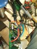
That's where the first bit of iffy news comes from as it was clear that all was not as it should be be. Close inspection (very close) as in best reading glasses and a magnifying glass revealed that the copper track on the back of the circuit board had lifted and broken away. I've fixed this, I think, by soldering some fine copper wires into the correct places on the back of the board. Whilst doing this I noticed that on the component side of the board directly beneath were the original resistor was fitted there is a rather scorched looking item which I think is a component, see photo. Its the component, if that's what it is, that is close to the "T2" and one of the legs on the new resistor.
However, I carried on with the job and went back to the tests you have guided me through. The first thing I noticed after connecting to the battery was the red LED wasn't on, then it was, then it wasn't, and that's how its been all evening during the tests without any pattern, and there doesn't seem to to be any dodgy connections.
I checked the supply and that was 37V. Then I checked as follows:
The new resistor which shows 37V at one end and 29V at the other end.
Then small regulator shows 14.5V at the IN end and 5V at the OUT end.
The large regulator shows 15V at both sides.
The motor halls were showing 5V.
The throttle signal was up to 4V but seemed intermittent.
The PAS was giving the 5V pulses.
The Mosfet test when connected to the red battery wire on control box and the readings showed 50k at the blue wire, 15k at the green and yellow wires. When connected to the black battery wire at the control box the readings showed 29k at the blue wire and 13k at the green and yellow wires.
I checked to see if there is any sign of life from the motor but unfortunately there is nothing.
Clearly all is not well and I wonder what comes next ???
Many thanks again

bobd
 

Attachments

thelarkbox

Esteemed Pedelecer
Aug 23, 2023
692
219
oxon
can you take more pics of the mystery item, it looks like a solderblob suspended in mid air or standing on 3 spider thin legs??
But the 2 not so clean solderpads just above to the right suggest its the underside of a component thats 'fallen' from there when overheated ???