Add a Throttle/solder a shunt

mart.hart

Pedelecer
Nov 10, 2008
81
0
I have been talking to d8veh who is a very helpfull chap about adding a throttle to my controller.
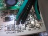
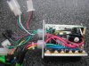
The problem is I have only 2 blocks of wire free.
1 A black and red
2. A black/red/white and green.
Both blocks on the top left of picture.
Both red wires follow the main power (so does the white) the other wires all go to the top left of the board.
Any Idea's
P1010046.jpg
 

mart.hart

Pedelecer
Nov 10, 2008
81
0
As for soldering the shunt, I get the impression that I should solder a line along from point A Taking in the boards solder to about point B third of the way along. This is just a line of solder and not coating all the way around ?Shunt.jpg
 

mart.hart

Pedelecer
Nov 10, 2008
81
0
No I just want a bog standard throttle. there are lots of ruts in this part of the word where you cant peddle.
 

Martin@e-bikeshop

Esteemed Pedelecer
Normally a bog standard throttle would have 3 wires going to it.
I can only imagine the extra wire in that 4 wire block is for a throttle with a LED readout of some sort.
If the red wire traces back to the power, and the white does too, i would imagine the cables you need are the red, green and black.. just a guess.. It's a little hard to see on the controller in the picture.

I presume your new bog standard throttle has 3 wires coming from it? Black, white and red?

Regards
Martin
 

mart.hart

Pedelecer
Nov 10, 2008
81
0
No the trottles I have seen have all been red/blue/black which dont match up with the 4 block of wires
 
D

Deleted member 4366

Guest
I believe that the connector with the red black green and white wires is for the throttle. If you want to fit your own throttle, it'll be the red, black and green wires and you'll need to change the connector.

For the controller to give power, the red and blue wires on the black connector need to be joined - normally by a switch on the LED panel but you can use any switch. The green and black with black connector are also for the LED panel for the variable PAS.

I think the red and black wires are for 36v lights. You can check with a meter whether there's 36v between them.

Green and black with white connector are for the brake switches because there's two of them

Red black and yellow is PAS

That leaves the white wire on the throttle connector, which has 36v on it for optional throttle LEDs. You can check by measuring between it and the thick battery blck or any other black.
 

Martin@e-bikeshop

Esteemed Pedelecer
Ok, so it has 3 wires from the throttle, as expected. Colour doesn't matter too much.
Is this a new controller? Is so did it not come with a wiring diagram?

You will need to plug it all in, add power and test the wires to see which ones you need to splice for the throttle. Alternatively you can pick up a new controller and buy a throttle at the same time to match. This obviously is more expense but it would save you cutting wires and a neater installation etc..

If it were me though I would test the wiring you have and splice the throttle in there.
Have a play with the throttle and that block of 4 wires there.. Black/Red/White/Green.

Regards
Martin
 

mart.hart

Pedelecer
Nov 10, 2008
81
0
Thanks d8veh that sound logical just a change of colour on one of the wires in the 4 wire block and the white is an extra power for led's. Connectors don't matter as this one is off my wife's bike I don't have any connectors on them as I soldered and shrink wrapped for room. They are new and from a Kudos sport I believe and sorry no wiring diagram.

Have I got the right ides with the shut ?
Thanks
Mart
 
D

Deleted member 4366

Guest
As for soldering the shunt, I get the impression that I should solder a line along from point A Taking in the boards solder to about point B third of the way along. This is just a line of solder and not coating all the way around ?View attachment 5306
You should coat the shunt in solder up to the mark. Here's an example:
 

Old_Dave

Esteemed Pedelecer
Sep 15, 2012
1,211
2
Dumfries & Galloway
Just to confirm.. It doesn't have to all the way around, (dont worry about the back) just copy the piccy shown by D8veh and bobs your aunt


Sent from my iPhone using Tapatalk
 

mart.hart

Pedelecer
Nov 10, 2008
81
0
Thanks for that Dave, if it had to be all the way around I would have given up before I started.

Mart
How did you know about my aunty Bob, we dont talk about him
 
Last edited:

mart.hart

Pedelecer
Nov 10, 2008
81
0
Update on the suspect 4 wire block.

White. wire feed in (so 37v)
Red wire. 5V
Black . ground
Green wire. HO. goes to a point on the board marked HO, so that could be Hall

Is the posative on a throttle 5v so its a switch or 37v so its a feed ????
 
Last edited:

Old_Dave

Esteemed Pedelecer
Sep 15, 2012
1,211
2
Dumfries & Galloway
So ignore the white for a mo, and it's red +, black -, green the throttle signal.

White would be used for the voltage led display if fitted


Sent from my iPhone using Tapatalk