
I measured the gears on my 3 speed Kalkhoff Agattu today:
1st gear 45 inches
2nd gear 60 inches
3rd gear 80 inches
(All are distance moved forward for 2 radians revolution of the pedals, ie for 1 pedal rev divided by pi)
Then in order to check the sprocket sizes I took the plastic chain cover off: one bolt on the inside at the back, then the cover eases forward off two clips at the front.
This is a view of the chain side with the chain guard removed. Note my Panasonic drive was made 17 Dec 2010.
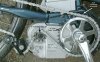
Using the sprockets sizes marked on the picture and the rear wheel circumference I worked out the rear hub ratio to be:
1st gear - 0.79
2nd gear - 1.04
3rd gear - 1.38
From what I have previously read about the Inter 3 hub the second gear should be direct 1:1 drive so my measurements agree with this within 4%.
I am very happy with these gears for my normal biking at 10 mph, but if ever I wanted to clip along a bit faster as I needed to last Monday night when keeping up with two push bike riders travelling at over 15 mph, I suppose the best thing would be to reduce the rear sprocket from 16 to say 14.
While I was inspecting the crank area I noticed a mysterious hole marked in the upper right of the picture, with connectors behind a flexible plastic sheet. Below is a close up picture, where you just make out an empty 4 pin female connector. I could also make out a 3 pin connector also not plugged in and the back of a third connector.

What are these connectors lurking under the plastic which obviously keeps the water out? Can I use them to gain access to what the electronics is doing?
I want to find out how I can fit an ammeter shunt to measure battery current. I don't suppose there could be a built in shunt and all I have to do is to connect plug in to the right connector, and then reseal the hole against water ingress?
I have not taken the plastic covers off the other side yet to see if a shunt could be installed there at the battery socket.
How do people fit ammeters to Kalkhoff's implementation of the Panasonic motor system?
1st gear 45 inches
2nd gear 60 inches
3rd gear 80 inches
(All are distance moved forward for 2 radians revolution of the pedals, ie for 1 pedal rev divided by pi)
Then in order to check the sprocket sizes I took the plastic chain cover off: one bolt on the inside at the back, then the cover eases forward off two clips at the front.
This is a view of the chain side with the chain guard removed. Note my Panasonic drive was made 17 Dec 2010.
Using the sprockets sizes marked on the picture and the rear wheel circumference I worked out the rear hub ratio to be:
1st gear - 0.79
2nd gear - 1.04
3rd gear - 1.38
From what I have previously read about the Inter 3 hub the second gear should be direct 1:1 drive so my measurements agree with this within 4%.
I am very happy with these gears for my normal biking at 10 mph, but if ever I wanted to clip along a bit faster as I needed to last Monday night when keeping up with two push bike riders travelling at over 15 mph, I suppose the best thing would be to reduce the rear sprocket from 16 to say 14.
While I was inspecting the crank area I noticed a mysterious hole marked in the upper right of the picture, with connectors behind a flexible plastic sheet. Below is a close up picture, where you just make out an empty 4 pin female connector. I could also make out a 3 pin connector also not plugged in and the back of a third connector.
What are these connectors lurking under the plastic which obviously keeps the water out? Can I use them to gain access to what the electronics is doing?
I want to find out how I can fit an ammeter shunt to measure battery current. I don't suppose there could be a built in shunt and all I have to do is to connect plug in to the right connector, and then reseal the hole against water ingress?
I have not taken the plastic covers off the other side yet to see if a shunt could be installed there at the battery socket.
How do people fit ammeters to Kalkhoff's implementation of the Panasonic motor system?


