
Great post Mr Bond, functionality seems similar to the E-crazyman contollers, only one area that seems to contradict some of the info on ES is the control of current using PWM. I'll need to go back over some threads to double check, I recall some posts suggesting only the voltage is controlled by PWM...
Alien Gents Special II - Improvments and Modifications
- Thread starter NRG
- Start date
I've not made much progress due to work, however, I've found the current limit settings for this controller to be out by a 5amp margin. I'm suspecting something is not quite right so I'm investigating the shunt and I've also asked for some help over on ES regarding the phase settings as I'm finding the controller a little to hot for my liking...
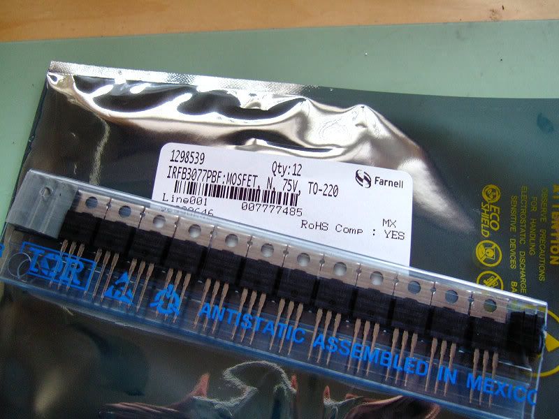
It would appear that +5amps 'error' is not uncommon and to be expected, its all down to how much resistance is in the 0v sense line and shunt. Many thanks to Jeremy Harris over on ES for this info and who also recommended an upgrade to FETs with a lower Rdson to lower the heat produced by them in operation. I'm also going to upgrade the caps with low ESR types and increase their voltage rating.
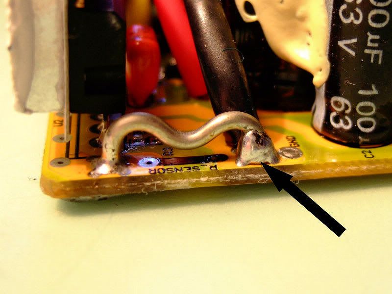
I did take a look at the shunt and found a build up of solder at each end, I used this technique on my old 24v controller on the Peugeot to increase amps but here I want to lower it so I removed as much as possible which resulted in about a 2amp drop....so its still out but not by much.
Here's the shunt and solder:
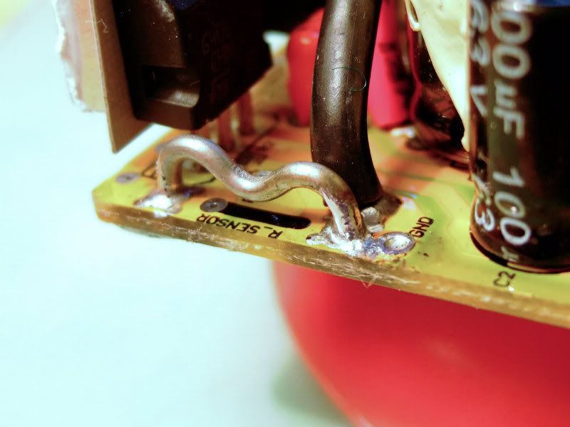
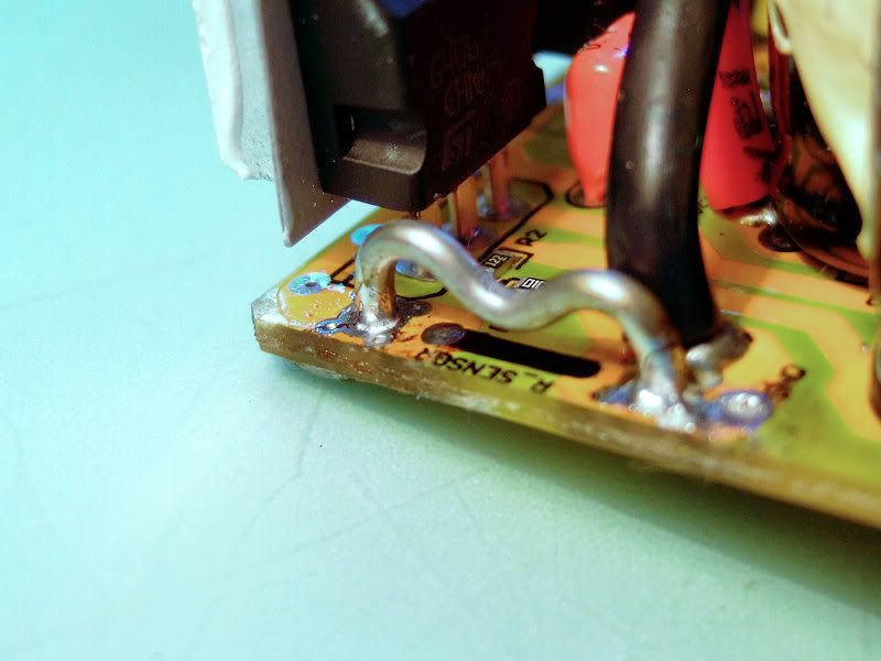
Removed as much as possible from both ends:
I've also done some more testing with the parameters and have settled on a rated current of 18amps and phase of 42....the 2.3~2.5 multiplier being about right. I don't want to push any further as TBH I can't tell the difference between setting at 20/46 or so. Also E-Crazyman recommends 15/35 with the Bafang motor so I'm pushing things as it is...I may even scale the phase back futher.
It also means I now know what to set the Alien controller to, at the moment is set too hot.
With 18/42 set I'm seeing ~21amps from the battery and good hill climbing performance, some concern over the nylon gears so will have to watch that.
FETs just arrived, waiting for caps now....why can't Farnell simply ship everything together...
I did take a look at the shunt and found a build up of solder at each end, I used this technique on my old 24v controller on the Peugeot to increase amps but here I want to lower it so I removed as much as possible which resulted in about a 2amp drop....so its still out but not by much.
Here's the shunt and solder:
Removed as much as possible from both ends:
I've also done some more testing with the parameters and have settled on a rated current of 18amps and phase of 42....the 2.3~2.5 multiplier being about right. I don't want to push any further as TBH I can't tell the difference between setting at 20/46 or so. Also E-Crazyman recommends 15/35 with the Bafang motor so I'm pushing things as it is...I may even scale the phase back futher.
It also means I now know what to set the Alien controller to, at the moment is set too hot.
With 18/42 set I'm seeing ~21amps from the battery and good hill climbing performance, some concern over the nylon gears so will have to watch that.
FETs just arrived, waiting for caps now....why can't Farnell simply ship everything together...
The upgrades to the controller are now done and its working well. Temperature is noticeably less and I've settled on 18/42 amps for the controller, I'll cut-n-paste some of the posts above over to my DIY Peugeot thread to keep it up-to-date.
For the Alien, I've added a programming port but not implemented the upgrades. I tried the recommended 15/35 amp but felt it lacked power so chose the same 18/42 as the Peugeot, this seems to work quite well and the bike is a pleasure to ride apart from a return of an annoying 'click' which I think is due to the chain...
For the Alien, I've added a programming port but not implemented the upgrades. I tried the recommended 15/35 amp but felt it lacked power so chose the same 18/42 as the Peugeot, this seems to work quite well and the bike is a pleasure to ride apart from a return of an annoying 'click' which I think is due to the chain...
The upgrades to the controller are now done and its working well. Temperature is noticeably less and I've settled on 18/42 amps for the controller, I'll cut-n-paste some of the posts above over to my DIY Peugeot thread to keep it up-to-date.
For the Alien, I've added a programming port but not implemented the upgrades. I tried the recommended 15/35 amp but felt it lacked power so chose the same 18/42 as the Peugeot, this seems to work quite well and the bike is a pleasure to ride apart from a return of an annoying 'click' which I think is due to the chain...
I just solved a problem click I`ve had with the Aurora by running around and tightening the spokes, one in particular was very loose.
Dave
When you say its working well - what has improved as a result of changing the controller? The switch with the 3 power levels - with the new controller settings are the different modes now providing different power levels?The upgrades to the controller are now done and its working well. Temperature is noticeably less and I've settled on 18/42 amps for the controller
John
The controller now runs cooler at higher current draw, higher current draw has improved hill climbing within the limits of the motor. The 3 way switch controls speed not power levels, however, as I've raised the current overall there's a touch more power in each setting. I haven't upgraded the Alien controller just played with the settings.
Last edited:
I feel a bit embarrassed about posting this given the very detailed technical posts in this thread, but I've got a tip about the centre stand (I'm assuming the GS2 has the same stand as the GS1 which I own!).
The centre stand is very low and I frequently used to catch it on things when going over obstructions/steep kerbs. That is until I found these side stands on ebay.
Big foot kick stand
It is lightweight but fully adjustable and takes the weight of my GS1 with loaded panniers. Also it comes with the same mounting kit as the original centre stand so you can just use the one you already have fitted.
Not a very technical tip, but there we go!
Actually, I've just remembered another one. If the GS1 has the same BB as the GS2 (cup and cone) then the only crank remover I could find that would fit (removal bolt has to be able to recess a good half inch back inside the threaded outer sleeve - most only recess to sit flush) was from a unicycle shop! It worked fine though when I changed to a Shimano sealed cartridge BB.
Thanks for the heads up on a cheap side stand.I feel a bit embarrassed about posting this given the very detailed technical posts in this thread, but I've got a tip about the centre stand (I'm assuming the GS2 has the same stand as the GS1 which I own!).
The centre stand is very low and I frequently used to catch it on things when going over obstructions/steep kerbs. That is until I found these side stands on ebay.
Big foot kick stand
It is lightweight but fully adjustable and takes the weight of my GS1 with loaded panniers. Also it comes with the same mounting kit as the original centre stand so you can just use the one you already have fitted.
Not a very technical tip, but there we go!
Actually, I've just remembered another one. If the GS1 has the same BB as the GS2 (cup and cone) then the only crank remover I could find that would fit (removal bolt has to be able to recess a good half inch back inside the threaded outer sleeve - most only recess to sit flush) was from a unicycle shop! It worked fine though when I changed to a Shimano sealed cartridge BB.
I removed the centre stand from my Aurora and had to fit two side stands to deal with the weight and even then on a windy day you had to be careful

Revisiting this thread. I don't think there's anything to control the current directly, because that would require analog power transistors. I think the controller limits current by scaling back the PWM and over-riding the throttle when actual current exceeds the max values.Great post Mr Bond, functionality seems similar to the E-crazyman contollers, only one area that seems to contradict some of the info on ES is the control of current using PWM. I'll need to go back over some threads to double check, I recall some posts suggesting only the voltage is controlled by PWM...
It's a shame and mildly annoying that the controllers come a bit underspecified on the components. And if the original manufacturer can't get it right, it would be nice if somebody could offer a service of modifying them. This is what Lyen does in the USA, right?
You mentioned adding a programming port to the other controller. Did you buy two? Or is this the original Alien controller? I thought the Alien controllers were the LDSZ design. They seem to have programming pads but nobody seems to have an equivalent bit of software for playing with them.
I wonder what C number current draw the plain old 36V10AHr Phylion LiOns can tolerate. You're now pushing it to 1.8C. The problem may be reduced life which of course won't show up immediately. I guess there's a whole battery thread in there.
Regarding the Big Foot side stand I've got one on the Aurora as it was lying around in the garage. It's usable but marginal. The problem is the severe rear weight bias and the centre mount. The front wheel tries to crab sideways if you set it to lean the bike too much. It's all alloy and the adjustment screw is a tiny 4mm bolt. It's easy to strip the threads and/or crush the tube. I think a side stand mounted near the rear axle would work better.
Yes, all it can control is the voltage via PWMRevisiting this thread. I don't think there's anything to control the current directly, because that would require analog power transistors. I think the controller limits current by scaling back the PWM and over-riding the throttle when actual current exceeds the max values.
The controllers are OK for lower power configurations but can be usefully improved very easily with new FETs and caps. Yes, Lyen offers modified controllers.It's a shame and mildly annoying that the controllers come a bit underspecified on the components. And if the original manufacturer can't get it right, it would be nice if somebody could offer a service of modifying them. This is what Lyen does in the USA, right?
I've added programming ports to both the E-Crazyamn controllers, I've been using one on my Peugeot conversion for some time and experimented with that one first.You mentioned adding a programming port to the other controller. Did you buy two? Or is this the original Alien controller? I thought the Alien controllers were the LDSZ design. They seem to have programming pads but nobody seems to have an equivalent bit of software for playing with them.
I think its the same battery as your Aurora, could be wrong...however, for the sake of the motor on both bikes and given the rather crude way that current limiting is done, I've scaled both bikes back to 16.5A rated and 38 phase, I really cant tell the difference on the road.I wonder what C number current draw the plain old 36V10AHr Phylion LiOns can tolerate. You're now pushing it to 1.8C. The problem may be reduced life which of course won't show up immediately. I guess there's a whole battery thread in there.
Hi NRG,The upgrades to the controller are now done and its working well. Temperature is noticeably less and I've settled on 18/42 amps for the controller, I'll cut-n-paste some of the posts above over to my DIY Peugeot thread to keep it up-to-date.
For the Alien, I've added a programming port but not implemented the upgrades. I tried the recommended 15/35 amp but felt it lacked power so chose the same 18/42 as the Peugeot, this seems to work quite well and the bike is a pleasure to ride apart from a return of an annoying 'click' which I think is due to the chain...
Any luck resolving that annoying click? I still have one as well with mine, I assumed it was the spokes, but having tightened these the click still persists, I took it to the local bike shop, but they were unable to solve it. I can still ride the bike ok, but it is really irritating.
This is a good thread to revisit, if NRG doesn't mind of courseRevisiting this thread. I don't think there's anything to control the current directly, because that would require analog power transistors. I think the controller limits current by scaling back the PWM and over-riding the throttle when actual current exceeds the max values.
Reading your comment over and over, i 'm not sure what you mean. What is 'scaling back' and 'overiding the throttle'.
Do you mean reducing the duty cycle of the PWM? By overiding throttle, you mean when current levels exceed what is expected from the throttle signal eg loading of the hub at low speed when perhaps the throttle is fully open?
I have discovered that my controller (supplied with my bafang hub) has some form of current limiting(i think).
I have added a potential divider (12turn potentiometer) to my throttle signal to prevent the full 4.3v signal being applied to the controller (WOT).
When cycling up a hill and putting some load on the hub i noticed the throttle leds flickering. This in inself in not uncommon because of volt sag, but what was unusual and unexpected was the frequency of pulses indicated that there was a form of current limiting in the controller. I might be wrong but I can only assume that because i have reduced my throttle signal voltage i am seeing current limiting actually happening.......?
Last edited:
I mean the controller notices the current going too high, so it reduces the PWM duty cycle, which reduces the power as if the throttle signal had been reduced. As the PWM duty cycle is reduced, it effectively reduces the average voltage seen by the motor. Less average voltage to the motor, means less average current taken by the motor. Which then brings it back under the current limit. It's as if you pulled back on the throttle to keep the current below a max level.This is a good thread to revisit, if NRG doesn't mind of course
Reading your comment over and over, i 'm not sure what you mean. What is 'scaling back' and 'overiding the throttle'.
Do you mean reducing the duty cycle of the PWM? By overiding throttle, you mean when current levels exceed what is expected from the throttle signal eg loading of the hub at low speed when perhaps the throttle is fully open?
There's a few people out there experimenting with variable current limits and a setting that can be changed on the fly as a way of eeking out battery capacity. I'm thinking of this as a way of being able to set an assist level rather than a speed. This would encourage you to go slower up hills instead of powering up them at relatively high speed which takes a lot of power. I'm undecided about this. It feels like you might as well go for a lower power motor and a controller with a low current limit. Sure, you'll go further on the same battery capacity, but you'll get less help from the assist.
I mean the controller notices the current going too high, so it reduces the PWM duty cycle, which reduces the power as if the throttle signal had been reduced./quote]
Yes that is what i thought you meant. But that would mean the current limit is set at one level and not variable.
What i believe is happening is the current limit level is also set by the throttle signal voltage not the current limit overiding the throttle (or 'as if throttle had been reduced')
Example 1, Full throttle, current limit threshold is high (you want power so current limiting is low).
Example 2, Half throttle current limit threshold is much lower reducing PWM.
Power is reduced (clamped, determined by throttle signal) only to be released to be clamped once again, hence the pulsing of the current flow.
I have an external current limiter already which works on a shunt resister and a simple circuit that reduces the throttle signal. However because of the differences between controllers it is not interchangable hence my potential divider setup on this controller. The idea of plodding up a hill with current limit set low is a very effective way of conserving battery power. I have managed to climb some of the steepest hills around my area with 4-5 amp of assistance.
TBH i'm really pleased that this simple fix has the desired effect of reducing battery consumption with out having to build external circuitry as before, but i really need to test it some more.
Yes i am probably taking a different approach than NRG who is trying to get more power out of his setup. But hey ho it's all interesting stuff. Not seen any magic cure for increasing speed yet though......
Carry on chaps
Last edited:
The primary control mechanism on these controllers is to vary the voltage by chopping the voltage at high frequency so the average voltage goes up and down. It's just like a switching power supply. They have 3 modes which represent a maximum average voltage. The throttle varies the average voltage up to the current mode's maximum. So the modes are like having a switchable battery, 36V, 30V, 24V (say). And in mid mode the throttle gives you 0-30V sent to the motor. For a given output voltage (say 20v), the motor will drive up to it's no load rpm at that speed. The falling torque curve and the power required (drag, gradient, etc) reaches a balance somewhere below this. So under steady state, the control mechanism is really a speed limiter. The motor speed will rise until everything balances for the voltage being provided. And that voltage is set by the mode and the throttle.
On top of this they have a current limiting feature. If the current goes too high, the average voltage is dropped until the motor takes less current. There's no direct current control, it's limited by reducing the available voltage.
What's ignored in all that is the Efficiency/BEMF/Torque/Current draw curve for the motor. Max efficiency doesn't line up with max current. With simple speed limiting the temptation is to throw the full 36V at the motor 100% PWM duty cycle even on hills. The speed falls and drops back to the max torque point, roughly max current point and take the full 15A (or whatever) from the battery. A better range strategy would be to only do this on very steep hills and for more gentle hills, just allow the speed to drop but keep the current under 10A (say). The reduced speed means reduced power needed, means reduced current draw, means longer range.
I think the reason your current limiter works is because it encourages you to slow down on hills where without it the E-assist encourages you to power up the hills as fast as the motor will work.
No problem with revisiting, its an interesting discussion.
As I understand it there is a current limit programable parameter controlled by the 116 firmware. Current through the shunt is meaured and if the limit is reached the controller cuts power abruptly, its a crude brick wall block. This is in addtion to the linear controll used with PWM.
If you look at my pics of the shunt earlier in the thread you'll see a black cct trace, this is the shunt sense trace used to monitor the current.
These 116 based controllers can only controll battery current where, as I understand it, the Kelly controllers can also directly controll phase current. With the 116 the phase current is guessed at from the ratio between battery and phase current set in s/w, hence the ratio setting of 2.3 t 2.5
The output voltage to the motor is proportional to the throttle voltage, these throttles therefore control speed not torque as in a car. The controllers seem to work like a charge pump where if the throttle is backed off (lowering voltage) when the motor is under load IE: climbing a hill, the actual current seen by the motor can be a number of times greater than the current pulled from the battery. You can feel this climbing a hill as backing off the throttle seems to mak no difference to the motor torque until it gets to a point where the throttle input voltage is demanding a lower speed than you re climbing at, only then does the power seem to fall away. But as we are using PWM lowering the motor voltage the current has to climb to maintain torque which puts the controller under greater stress....
I know what you're saying from what it feels like. But I can't see how. Let's take some notional figures. Max speed 300rpm and we're currently going up a hill at 150rpm. The battery sees 36v10A for 350W and at 100% throttle so does the motor. We chop the throttle to 50% and the battery still sees 36V10A but the motor sees/draws 18V20A, same 350W so we don't slow down. Is that possible? Or are we moving across the motor graphs for 36v and 18v and shifting from max torque to max current or something. Meanwhile the heat dissipated in the FETs is I^2R and since R is constant the heat went up 4 times.The controllers seem to work like a charge pump where if the throttle is backed off (lowering voltage) when the motor is under load IE: climbing a hill, the actual current seen by the motor can be a number of times greater than the current pulled from the battery. You can feel this climbing a hill as backing off the throttle seems to mak no difference to the motor torque until it gets to a point where the throttle input voltage is demanding a lower speed than you re climbing at, only then does the power seem to fall away. But as we are using PWM lowering the motor voltage the current has to climb to maintain torque which puts the controller under greater stress....
Confused!
Yes, its possible. The controllers are similar to a buck converter (not charge pump as I said above) and to maintain power with a loss of voltage the motor current must rise. See the ES thread I referenced in an earlier post:
Endless-sphere.com • View topic - **Important** reality check on motor, voltage, current etc.
Endless-sphere.com • View topic - **Important** reality check on motor, voltage, current etc.
Last edited:
Thanks for that. Now on Page 9 of 24
Understanding is coming slowly. Very important point I think.
This relates directly to the guess of phase current limit should be 2.5* battery current limit.There's been a suggestion or two here that the Infineon/Xiechang controllers measure and control phase current. This isn't strictly true, they only actually measure battery current, they guess at phase current from other factors, like the pulse width and battery current for a given throttle demand and then limit accordingly.
I'll continue reading while bearing in mind the strategy of deliberately limiting battery current externally to increase range.
Related Articles
-
 MTF Enterprises announces acquisition of EMU Electric Bikes
- Started by: Pedelecs
-
 Wisper 806T folding bike wins Which? ‘Best Buy’
- Started by: Pedelecs
-
 Sustrans calls for protected cycle lanes
- Started by: Pedelecs
-
 Amazon launch their first UK e-cargo micromobility hub
- Started by: Pedelecs
