How I got the breadboard working
4 posts ago I was stumped,
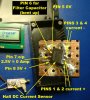
I got all the connections soldered, but the device is not working - the output should be sitting at half way between the 5v and 0V for no current flowing through the heavy current connectors - but it seems to be sitting at 5V, furthermore the Hall device is drawing no current from the 5V supply - it should be drawing about 10 mA.
Perhaps I have somehow wrecked the device. I have now ordered a tiny adapter board which will properly mount the SOIC style package and convert to an 8 Pin DIL which will match the holes on the strip board. I may have to order some more Hall sensors at £4.50 each.
It turned out that the output (pin 7) was a dry joint - continuity when I pressed the probe down on the pin, but when I released the pressure the joint opened.
The next thing that happened during bench testing was the filter capacitor which I installed on the bent up leg (pin 6) got knocked and the leg broke off at the package. So, until I get a new Hall chip and install it on a proper tiny header board which has now arrived, I have had to operate without this capacitor. A pity because I could see was reducing noise from the Hall sensor.
My next blunder happened while installing the Hall sensor on the bike. As I plugged the battery lead into the heavy connectors, one connector pulled the copper strips off the PCB. I scrapped these connectors, soldered to the board and connected them with some flexible copper desolder braid to prevent strain on the joint.
I have calibrated the Hall by comparing with my digital multimeter at 1 Amp . The Hall is very linear. When I tested it at 6Amps it was within 2%.
Everything fixed I have been out on the bike measuring the current. But the largest current I have seen with averaging by the program I have written for the Picaxe (Averaging of 100 ADC samples taken in 2 seconds) is around 8 Amps. 8A*25.5V = 204 Watts from the battery.
That is what I got in the original post of this thread.
So back to the experimental bench to see if I can work out why this is different from the larger currents I measured using my digital multimeter on the millivolt range measuring the drop across a current shunt and reported earlier in this thread, here:
Flecc was right ~400watts. One of the measurements is wrong and I must find out which it is.

 MTF Enterprises announces acquisition of EMU Electric Bikes
 Wisper 806T folding bike wins Which? ‘Best Buy’
 Sustrans calls for protected cycle lanes
 Amazon launch their first UK e-cargo micromobility hub