Gazelle Orange Innergy rebuild

Miktavus

Finding my (electric) wheels
Feb 20, 2021
11
1
York
I previously posted regarding refurbing an unreliable Orange Innergy https://www.pedelecs.co.uk/forum/threads/gazelle-orange-innergy-intermittent-loss-of-power-assist-function.40446/#post-604040 and the responses guided me in the right direction - thanks. The main guidance I followed was here https://otapi.medium.com/renew-a-faulty-e-bike-ffa566e3a855

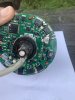
I removed the hub mounted controller and soldered on three motor phase wires connected to a S6-61 controller with a S866 display, and installed a PAS sensor. Playing around with the programming has resulted in satisfactorily power assisted bike, but the performance is a bit rough. I suspect this may be due to the lack of Hall sensors.

When I removed the original controller circuit board I cut two thin wires (as well as the 3 phases) which, I think, were both brown. I did nothing with them but suspect they may be the +ve and GND for the Hall sensor in the motor. Would this be correct? If so could they be connected to the 5v and GND wires on the 5 pole "Motor Hall" connection plug on the controller? And, as the wires were both the same colour is polarity important, is it a matter of experimentation, and would wrong connection cause damage?

Many thanks for your advice - the forum has helped me immensely.

Mike
 

Miktavus

Finding my (electric) wheels
Feb 20, 2021
11
1
York
Additional info - I checked the original controller circuit board and have identified which of the brown wires is connected to ground with a continuity meter, so therefore I know which is which of the two wires in the hub. That should rule out potentially damaging experimentation.

Mike
 

vfr400

Esteemed Pedelecer
Jun 12, 2011
9,822
3,986
Basildon
The two extra wires are probably for a temperature or speed sensor. You should have followed them to see where they went. Whatever they're for, you can't use them for anything useful.

There are some settings in the LCD that might improve the rough running. Did you set P1= number of magnets in the motor x reduction ratio? Also see if changing C2 does anything.

Some controllers just don't like to work with some motors, and some are better than others when it comes to sensorless operation. The KU63 from BMSBattery has always been good at working with difficult motors.

The guy in the video used mains cable to connect his motor. That's not a good idea. Proper motor cables with the right controller connections and high grade PTFE coated wire are available from Ebay, and they don't cost much. Also, using hot-melt glue to fix a controller that can become hot isn't a good idea either. he probably found out that not long after he published that article.
 
Last edited:

Miktavus

Finding my (electric) wheels
Feb 20, 2021
11
1
York
Thanks, the two wires emerged from the motor coils and were soldered straight into the round controller circuit board in the hub. Unfortunately it was not possible to determine their function from that, though if they're not Hall sensor related it saves me the hassle of opening up the hub again and achieving nothing. I'm happy that the bike is usable. Although I've used 3 core mains cable as he did ( I had some spare), I have used good quality connectors. I also wasn't impressed by his "agricultural" approach to the controller mounting and have located mine in a bag at the back under the saddle.
 

vfr400

Esteemed Pedelecer
Jun 12, 2011
9,822
3,986
Basildon
Thanks, the two wires emerged from the motor coils and were soldered straight into the round controller circuit board in the hub. Unfortunately it was not possible to determine their function from that, though if they're not Hall sensor related it saves me the hassle of opening up the hub again and achieving nothing. I'm happy that the bike is usable. Although I've used 3 core mains cable as he did ( I had some spare), I have used good quality connectors. I also wasn't impressed by his "agricultural" approach to the controller mounting and have located mine in a bag at the back under the saddle.
It's vaguely possible that your motor cable might be contributing to the rough running. I can't say that it is because I don't know enough about high frequency pulses, but I do know that the Chinese wouldn't use expensive PTFE coated 30 amp cable if they didn't have to. I have run a sensorless motor before with mains cable, but it was a big slow one and I used heavy duty cable with silicone coated wires - the stuff you use for cookers and electric fires.
 

Reda

Just Joined
Jun 19, 2023
1
0
Hi guys, i need to repair my ebike gazelle innergy motor, but i cant open the cover .
I removed all the bolts (6 bolts), i did tap slightly on the other part of the axe, but the cover dont move at all, what should i do please. ? Thanks
 

saneagle

Esteemed Pedelecer
Oct 10, 2010
4,346
2,138
Telford
Hi guys, i need to repair my ebike gazelle innergy motor, but i cant open the cover .
I removed all the bolts (6 bolts), i did tap slightly on the other part of the axe, but the cover dont move at all, what should i do please. ? Thanks
The side unscrews. You need to make a tool that goes into the holes so that you can rotate it. You don't need a fancy one like the one in the video - just enough to turn it. It helps a lot if you warm up the main part of the motor by waving a hot air gun between the spokes until the hub is just getting to hot to touch.

 
  • Like
Reactions: Reda

Rogern

Pedelecer
Jul 13, 2023
25
0
I have inherited a gazelle Orange Inergy plus ebike with a dud battery; I am nowhere near an agent for this make. I have bought a new pannier battery and have ordered a KT LCD 5 display, a 12 magnet 3 pin PAS and a 24v 20 amp KT controller ( brushless motor) 250W 350W. I am following the Gazelle Orange Innergy rebuild on OTAPI but I am struggling to remove the hub cover to reveal the original controller and remove it as suggested. I have removed the bolts securing it but I am now stuck. Any advice on this rebuild would gratefully received!
 

Rogern

Pedelecer
Jul 13, 2023
25
0
I’ve read the suggestion on making a tool to remove the cover. - any templates for this?
 

saneagle

Esteemed Pedelecer
Oct 10, 2010
4,346
2,138
Telford
I’ve read the suggestion on making a tool to remove the cover. - any templates for this?
Make a template out of thin card and a pair of scissors. When you have the correct profile, poke the holes with a pencil or Phillips screwdriver.
 

Rogern

Pedelecer
Jul 13, 2023
25
0
I have tried to make a tool to remove the cover on the hub with no success - this is the key to the rebuild! Has anyone out there got access to the tool required or know where I can buy one ?
 

saneagle

Esteemed Pedelecer
Oct 10, 2010
4,346
2,138
Telford
Unlike the video the cover is on the same side as the wire - see attached file!
That's not a screw-on cover. What's on the other side of the motor? If it's the same or has nothing, you just remove everything from the axle and hit it with a mallet until the opposite side pops. If you had shown photos in the first place, it would have saved a lot of time and effort.
 
Last edited:

Nealh

Esteemed Pedelecer
Aug 7, 2014
20,193
8,241
60
West Sx RH
As D8veh has said pics would have been best to start with.
The face plate is face fixed via 6 screws, one has to remove all axle nuts on the ooposite side which often keep a seal washer in place and then if the motor isn't rusted due to water ingress should tap out ( with a block of wood and decent blow from a hammer on the axle end.
 

saneagle

Esteemed Pedelecer
Oct 10, 2010
4,346
2,138
Telford
Just bash the axle through with a heavy mallet. You can also use a large hammer and a block of wood. If you don't have a hammer or mallet that's heavy enough, screw the nut on the axle so that it's flush with the end of the axle, hold the wheel horizontal about 2 to 3 feet from the ground and let go.
 

Rogern

Pedelecer
Jul 13, 2023
25
0
I dropped the wheel on the opposite axle( with the nut flush) and the cover popped off. Thanks for all your tips. I now have the controller on top of the motor, as per photo. The controller seems to be secured in place by a bearing and several wires between it and the motor. What do you suggest to do now? Photo attached
 

Attachments

saneagle

Esteemed Pedelecer
Oct 10, 2010
4,346
2,138
Telford
It's difficult to see from the photo, but it looks like a black seal outside the bearing. I would say that the bearing is fitted to a shoulder and it just pulls off, so you need a three-legged puller to get it off and the seal will come with it.
 

Rogern

Pedelecer
Jul 13, 2023
25
0
You are correct, the black seal just slips off then the bearing needs to be removed to allow access to the controller. There are three orange clips on the outside of the controller and two small star bolts partially hidden by the bearing, Next mission - remove the bearing!
 

Rogern

Pedelecer
Jul 13, 2023
25
0
I’m wondering if the controller can be removed by breaking the Bakelite - there only seems to be three copper connections and two brown wires attached to it. The bearing may be difficult to put back.
 

Advertisers