Gazelle Orange Innergy rebuild

saneagle

Esteemed Pedelecer
Oct 10, 2010
4,346
2,138
Telford
I’m wondering if the controller can be removed by breaking the Bakelite - there only seems to be three copper connections and two brown wires attached to it. The bearing may be difficult to put back.
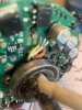
Better to keep the controller intact if you can. Borrow a puller from a friend if you don't have one.

The photos are good. They'll help anybody else that has this motor.

 
Last edited:

Rogern

Pedelecer
Jul 13, 2023
25
0
I’ve ordered that one on eBay; is it difficult to put the bearing back? You’ll have to excuse my naivety!!
 

Rogern

Pedelecer
Jul 13, 2023
25
0
On further inspection, I think that the controller can be removed without removing the bearing. Attached to the underneath there are only the three copper wires attached to the motor and two brown mystery wires. The cable can be replaced through the slot above the bearing. One question - do the three copper wires have to be attached in any particular order. The cable end has white, yellow and Orange attached to the controller? I’ve attached some more detailed photos.
 

Attachments

saneagle

Esteemed Pedelecer
Oct 10, 2010
4,346
2,138
Telford
It should be pretty easy to refit the bearing by tapping it back on. Only tap the middle bit, not the outer ring. If you heat it up first, it might just drop on.

I wouldn't know what those three wires are for without knowing what's the other end attaches to, and yes they have to go back in the same sequence only if you want to use that controller again. If you're going to use an external controller, you will chuck the wires. All you need is the three phase wire connections to the motor, to which you attach you're new motor cable.
 
Last edited:

Rogern

Pedelecer
Jul 13, 2023
25
0
On reflection, I think I will remove the bearing and retain the Bakelite controller and cut the wires - I can connect the three phase wires to a new cable on top of the disconnected controller - I feel thé this would provide protection from any damage to the connectors from heat generated by the motor. All the other parts have arrived - another mission is to connect the three phase wire to the controller connection, which has a five pin connector.
 

Rogern

Pedelecer
Jul 13, 2023
25
0
I dont think I need a speed sensor at this stage - but I really need to know is which wires in the nine pin connector correspond with the the three from the motor. Are they the sales colours as on the motor ie Orange white and yellow, if I get this wrong it could damage the controller!
 

Rogern

Pedelecer
Jul 13, 2023
25
0
I have found a diagram of the wiring of the 9 hole motor connector - the wire colours of the controller don’t match those of the hub motor. Without Hall is it still important to fit them in the right order, if so, just trial and error I guess.
 

saneagle

Esteemed Pedelecer
Oct 10, 2010
4,346
2,138
Telford
I dont think I need a speed sensor at this stage - but I really need to know is which wires in the nine pin connector correspond with the the three from the motor. Are they the sales colours as on the motor ie Orange white and yellow, if I get this wrong it could damage the controller!
It doesn't matter at this stage, especially if you have bullet connectors at the other end. If the motor goes backwards, you just swap any pair. It's only when you have hall sensors that you have to worry about the connection sequence because there are 36 combinations.
 

Rogern

Pedelecer
Jul 13, 2023
25
0
Thanks for all your advice saneagle, all parts on order for reassembly. Just one last question - the 5 volt red connection on the motor to controller cable, is that for the lights ?
 

saneagle

Esteemed Pedelecer
Oct 10, 2010
4,346
2,138
Telford
Thanks for all your advice saneagle, all parts on order for reassembly. Just one last question - the 5 volt red connection on the motor to controller cable, is that for the lights ?
Not too shure what you mean. Is it in the cable coming out of the motor? If so, what other wires are in the cable and what's on the handlebars, like switches, display, power selector, etc. is there a pedal sensor in the bottom bracket because i didn't see anything in the motor?
 

Rogern

Pedelecer
Jul 13, 2023
25
0
The nine pin socket coming from the controller - it has the three main connections for the cables coming from the motor. I’m not using the other six- however there is a unused 5 volt connection amongst them, I wondered if that was for the lights - the others are for HALL sensors and an earth in the middle. The PAS is connected to the controller with it’s own dedicated connection ( I have purchased a separate kit rather than use the one fitted by Gazelle - these work very well on my hybrid with a Swytch conversion).
 

Rogern

Pedelecer
Jul 13, 2023
25
0
Another query you may be able to help me with- what is the best way connect the three wires from the motor to the cable? Most of the standard connectors are too clunky and I’m wondering if there is any heat produced by the motor that I have to consider!
 

saneagle

Esteemed Pedelecer
Oct 10, 2010
4,346
2,138
Telford
Another query you may be able to help me with- what is the best way connect the three wires from the motor to the cable? Most of the standard connectors are too clunky and I’m wondering if there is any heat produced by the motor that I have to consider!
The three thick wires are the motor power wires. There are 5 thin red wires that work the hall sensors, red and black provide the power for them. Green, blue and yellow are the signal wires. There is also a white wire for the internal speed sensor signal if you have one. The speed sensor also gets its power from the black and red.

The hall sensors only need low power that comes directly from the controller's 5v regulator that also provides the power for the controller cpu, pedal sensor, brake sensors, pedal sensor and throttle. You can't connect anything to that 5v rail that uses real power, like lights.

The best way to connect wires is to solder them, but that leaves the wheel still connected when you take it out to change a tyre, which is a minor inconvenience, not a show stopper.
 

Rogern

Pedelecer
Jul 13, 2023
25
0
I have just reassembled my gazelle ebike but the display doesn’t seem to work with the controller. The controller is a KT24Z WSRD 24V 20A for brushless motors. - the display is a KT LCD5. Any advice on how to match these would be more than helpful!
 

Advertisers