Hi there,
My name's John, originally from Bristol but now living in Southern Sweden. I was just going to introduce myself here but I saw that some others were posting requests for help so I'll do so here also, hope that's OK as it'll kinda kill two birds with one stone.
I run a mobile coffee bike here and I bought a e-cargo bike from China (1st mistake). There was no power when I switched the battery on last week so I bough a multimeter and traced the fault to the actual ignition style switch on the no-brand battery that was supplied. Great, I thought, so I decided to strip the lock down (2nd mistake) and broke the actual mechanism - springs, ball bearings everywhere, have no idea how to put it back together.
So now I'm in a situation where I need to replace the lock but I can't wait for the most likely similarly inferior product to arrive from China in 2 months. Sooo...
I'm thinking that a simple rocker or push button switch would be fine to replace it but I'm having a devil of a time finding one that is rated to handle 48 volts DC and also 10 amps. I've been on RS Components and not found anything as well as ebay and Amazon.
Is there anybody here that could offer any advice or preferably a link to something that worked for them? The bike when loaded weighs at least 300 kilos and is impossible to ride without assistance so I'm unable to work - any help gratefully received. I'll upload some pictures too.
Thanks!!
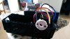
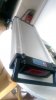 Here's the battery
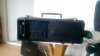
 Here's the lock mechanism, the white part contained the switch
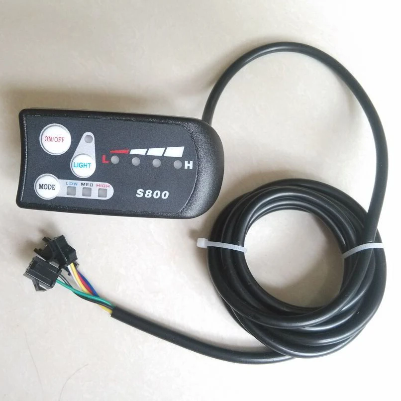
 Here's the switch that connects to the end. I'm thinking I'd just need a 48v 10amp switch but I can't find one!
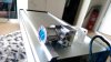
 And here's my bike!
 ")
My name's John, originally from Bristol but now living in Southern Sweden. I was just going to introduce myself here but I saw that some others were posting requests for help so I'll do so here also, hope that's OK as it'll kinda kill two birds with one stone.
I run a mobile coffee bike here and I bought a e-cargo bike from China (1st mistake). There was no power when I switched the battery on last week so I bough a multimeter and traced the fault to the actual ignition style switch on the no-brand battery that was supplied. Great, I thought, so I decided to strip the lock down (2nd mistake) and broke the actual mechanism - springs, ball bearings everywhere, have no idea how to put it back together.
So now I'm in a situation where I need to replace the lock but I can't wait for the most likely similarly inferior product to arrive from China in 2 months. Sooo...
I'm thinking that a simple rocker or push button switch would be fine to replace it but I'm having a devil of a time finding one that is rated to handle 48 volts DC and also 10 amps. I've been on RS Components and not found anything as well as ebay and Amazon.
Is there anybody here that could offer any advice or preferably a link to something that worked for them? The bike when loaded weighs at least 300 kilos and is impossible to ride without assistance so I'm unable to work - any help gratefully received. I'll upload some pictures too.
Thanks!!
Here's the battery Here's the lock mechanism, the white part contained the switch Here's the switch that connects to the end. I'm thinking I'd just need a 48v 10amp switch but I can't find one! And here's my bike!