Izip Skyline Shut Down Problem

Whurlyburd

Finding my (electric) wheels
Jul 24, 2013
16
0
Montrose, Angus
DSC_1226.jpg

Not sure how to do that but here goes.......

I really do very much appreciate the help you folks are giving!!!
 
Last edited:
D

Deleted member 4366

Guest
Orange and red are probably the battery voltage ones. Check them with a meter before bridging.
 
D

Deleted member 4366

Guest
I just looked again, and I see it has 5 wires. Mine only had four. I'm guessing that it'll use the 5v from the controller for the supply to the microprocessor rather than its own regulator. You need to check from the black to each of the other wires with it switched on and off.
 

shemozzle999

Esteemed Pedelecer
Sep 28, 2009
2,826
686
Hmmm don't know why it has 5 wires I was expecting to see an extra aux switch maybe for lighting.
Anyway I wonder if we can find the right wire that carries the assist voltage level signal.
On the good one can you check which wire changes voltage level when you press the assist button and can you record the 3 voltages if you find it, be careful as one of them will be carrying the full battery voltage.
 
D

Deleted member 4366

Guest
I just looked at it again and wondered why it has that large resistor. It looks like the track goes from the resistor to a regulator hiding under the capacitor. I'm now thinking tha it's the other way round, and the red wire is providing the 5v for the controller. It looks like pink is 24v going through the diode and then the resistor to the regulator, so that leaves blue or mauve as the 24v return and the other as the signal wire; however, in the photo it looks like both are connected to the processor, in which case it's a bit more complcated
 

Whurlyburd

Finding my (electric) wheels
Jul 24, 2013
16
0
Montrose, Angus
Gents,

Two clearer pics of the pcb FYI.

This morning I tested the wires at the pcb both with power on and with power off...these were my findings:

POWER OFF
Red to Black = 27v
The other three wires showed nothing

POWER ON
Red to Black = 27v
pink to purple + 17.75v irrespective of assist setting
pink to blue = 17.75v irrespective of assist setting
purple to blue = multimeter (Fluke Auto) would not read

My fingers found that the large resistor grew extremely hot very quickly!

Hope this helps in the quest!
 

Attachments

Last edited:
D

Deleted member 4366

Guest
You should keep your black probe on the black wire, and then probe each of the other wires with the power switch on the display on and off. No need to check anything else.

The resistor would normally get hot because it's cutting down the 27v for the regulator.

I can figure out some of it, but it's difficult to trace all the wiring. As far as I can see, the on/off switch switches a tansistor on the back of the board (the big black component near where the wires are soldered). It's soldering looks a bit messy, so have a good look that its there's no bridge between the three legs.. I think it might join the blaclk to the pink when it switches on, but it's difficult to see. You could try putting your meter on "beep" (continuity) and see if it beeps when you probe black and pink with the power switch on and off.

You could alo try resoldering the five wires just to make sure that they're OK.

After that, I'm running out of ideas unless your voltage measurements show something new.
 
D

Deleted member 4366

Guest
I just had another thought. As far as II can see, it's the processor that initiates the switching, so either it loses power and re-initialises to off, or something is telling it to switch off, i.e. the power switch. I'm wondering if the panel casing has got distorted, and it touches the switch to switch off - maybe when it gets warm. Does it still cut-out with the case open?

You might also want to have a look on the controller solder joints for the 5 wires.
 

Whurlyburd

Finding my (electric) wheels
Jul 24, 2013
16
0
Montrose, Angus
Followed your instructions:

My meter automatically sources to voltage/resistance etc.

POWER OFF
Red = 28v
Pink = 28v
Purple = 4.2
Blue = 8.4

POWER ON
Red = 28v
Pink = 0v
Purple = 0v
Blue = 0v

However after touching the blue wire the panel lights have gone out and will not switch back on again :(
The solder points are OK, what you are seeing is messy lacquer

The case is OK as I am testing the pcb outside the casing with the same results
 
Last edited:
D

Deleted member 4366

Guest
OK, that's like I thought. Blue and purple are probably data, and switching is done between the black and the pink, so the only thing to try is bridging black and pink to see if the controller works with the throttle and/or a default level of PAS.
 
D

Deleted member 4366

Guest
If the lights have gone out, check again between black and the nearest leg of the big resistor to see if you still have power (27v). Touching the blue shouldn't have any effect. It looks like there's a resistor on that output so the processor should be protected. There's nothing else on that line.
 

Whurlyburd

Finding my (electric) wheels
Jul 24, 2013
16
0
Montrose, Angus
Unfortunately there is 0v at the resistor

Bridging the pink and black does nothing...I do not have 24v at the pink anymore.

I found this site while trolling this morning and parts from this company might just be the answer?
Bicycle Network
 
Last edited:
D

Deleted member 4366

Guest
It might seem that you've gone backwards, but you've actually gone forward. You now need to find whether it's the black or red wire that's had it's connection broken. These are connected to the controller - nothing to do with the panel. You could stamp on the panel, but you should still have 27v on those two wires.

What you need to do now is put your black probe on the black wire at the battery and the red probe to the red wire at the panel, and vice versa. One way, you'll get 27v to tell which wire is broken. Then all you need to do is probe at every stage back to the controller to see where the interruption is. Then, hopefully, your problem will be solved.
 

Whurlyburd

Finding my (electric) wheels
Jul 24, 2013
16
0
Montrose, Angus
I have 24v across red and black at the panel..there is not a connection issue at the panel from these two wires.

Prior to the testing I had 24v at the pink when the panel was turned on, now I have no lights and no volts at the pink when turned on.
 
D

Deleted member 4366

Guest
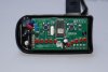
OK, my mistake. Originally I thought that the resistor was joined to the red, but now it looks like it's connected to the pink, which doesn't make sense. it's really tricky figuring it out from a photo - much easier with a meter.

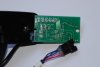
I can't understand it because normally, the 27v would go through a diode (the black thing near the red wire that shows the current direction as downwards), then through the big resistor to the "in " leg of the regulator, which is the one nearest the edge of the board, so everything looks right, but it doesn't tie up with your measurements.

My reckoning is that the 27v switches sides down the blue capacitor leg, then goes to the power switch. The switch latches the transistor, which then powers the panel and passes the 27v back down the pink wire for the controller. I think the latching is done by the processor via the small transistor. That's why you have to hold it for a bit to switch on. When you press and hold the power button again for a longer time, the logic in the processor detects it and powers up the small transistor that de-latches the main one - or something similar. It's possible that there'es something that I can't see in the photo, but I'm sure that my logic is correct. The pink can't be 0v because the diode would be the wrong way round.

Maybe it would be better to look at the controller rather than the panel to see where its regulator gets its power from. I bet it's the pink wire.
 
D

Deleted member 4366

Guest
After doing some tests on similar meters, I think I've got this one figured out. I got a bit confused by post #30, where the results must be reversed between on and off.

-The red wire is the 24v supply.
- The pink wire is switched on to the 24v when the panel is on. This 24v then goes back to the controller to supply the 12v regulator, which then supplies the 5v regulator.
- The black wire is 0v
- The blue and purple wires are TX and RX data to the controller.

The 24v comes in to a FET, which blocks it. There's a branch to the power switch, which when pressed opens the FET to pass the 24v through the big resistor to the 5v regulator, which then powers the main processor. The main processor then gives an output to a small transistor that latches the FET on. When you press the power button again, the processor logic switches off the small transistor which then switches the FET off again, so everything powers down.

There's a voltage splitter that gives a voltage measurement to the processor. It uses logic to switch on/off the battery LEDs.

The PAS level switch is also sensed by the processor, which then uses logic to switch on/off the PAS level LEDs, and at the same time sends data to the controller to set PAS levels.

There could be some hand-shaking procedure between the controller and panel necessary for the controller to start operating as there is TX and RX.

Shorting the pink and red wires will power up the controller. It might work on throttle like that, but the controller might prevent power output if it doesn't detect the panel.
 
Last edited by a moderator:
D

Deleted member 4366

Guest
For anybody with the four-wire type (King meter 790, 810, etc), I have checked inputs and outputs. The power section works the same.The red wire is battery voltage, the blue the return to the controller power, and black 0v, but the forth wire (green) has an analogue output. Pas level 1 = 1v; Pas level 2 = 2v; Pas level 3 = 3v; 6km button changes output to 4v when pressed. You can therefore bypass the meter if it becomes faulty by connecting the red and blue wires together. I don't know what happens if there's 0v on the signal. Maybe it won't give any power, but if so, you can make a voltage splitter out of two resistors between the PAS 5v and 0v to give a fixed PAS level.
4.7K and 1.2K resistors will fix level 1
3.3k and 2.2k will give levels 2 and 3 depending which way round you put them.

You could also use a 10K preset, which might be easier. You can then just turn it until you get the level you want and leave it like that. Vrt Encl Preset 10k Order Code: UH16S from Maplin - 69p
http://www.maplin.co.uk/sub-miniature-fully-enclosed-carbon-preset-potentiometers-6499

The resistors cost about 20p each from an electronics shop.
 
Last edited by a moderator: