Powabyke Xbyke controller replacement

braham

Finding my (electric) wheels
Apr 13, 2017
11
0
44
oxford
I am very new to this website as a member but I have been following threads here for a little while.
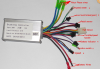
My Xbyke has burnt its controller. Having looked around for a replacement controller I didn't find anything for a like a like for like replacement. I decided to take a small gamble on a controller I saw on AliExpress see picture below.
The controller has arrived, and I have changed it. even though I am getting the throtlle light on the motor is not kick in. The controller I got has far more wires than the original on the Xbyke but I am able to find all the cable and connection necessary for the xbyke, it's just that there many other cables not connected to something.
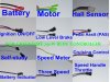
Does anyone has an idea why the controller is not functioning? The non-connected wires are:
- speed meter
-low brake level brake
- battery indicator
- ignition switch
- speed
controller.png
Any help would be very welcome.
thank you
 
D

Deleted member 4366

Guest
Normally, you have to connect the ignition switch to the battery positive (ideally via a switch), but it worries me that it's black. they're normally red, pink orange or blue.

To be sure, you would have to open the controller and see where that wire goes. If it joins to the big resistor, then it connects to the battery positive on the outside.

Here's what I mean:


the big resistor is the thing standing up at the right end. The red wire is the ignition wire that's soldered to a pad adjacent to the resistor's leg, often marked VCC.

To get the controller apart, remove the screws from the wires end and the screws along the side. the contents should then slide out like in the photo.

Another test that might save all that trouble is to set your meter to beep (continuity), then test between the ignition wire and the battery indicator wire. If it beeps, you connect it to the battery positive.

The other wires are all optional. The speed one is probably for a three-speed switch.

Speed meter pulses for some speed reading devices.

The battery indicator is simply a branch off the battery wire (could be before or after the ignition switch, so might only be live when switched on).

The low-level brake is for the normal brake switch wires. If you have two, you can join them together (parallel) to that connector or just connect the back brake one.

The rest are obvious.
 
  • Like
Reactions: braham

braham

Finding my (electric) wheels
Apr 13, 2017
11
0
44
oxford
Hi d8veh
I have no words to thank you enough with. This is very helpful.
I have check the actual controller I have with me, the ignition is not black (phew!), however it looks like it's 2 wires (red and purple) according to another picture on the same product page on Aliexpress. I will attach it below:
controller1.jpg

In this case, do I connect both to the battery positive on the outside?

Thanks
 

braham

Finding my (electric) wheels
Apr 13, 2017
11
0
44
oxford
I have just opened the controller and here my findings:
- purple have vcc making but about an inch away from the big resistor:(
- the red is close to the resistor but no VCC mark or maybe I haven't seen it because of all the stuff condensed in one place:(
 
D

Deleted member 4366

Guest
When you have two wires, all you need to do is connect them together. One will be connected to the positive battery wire on the pcb. The other, when connected to it, will carry that voltage back to vcc to power the controller. My guess is that the red is the permanent live and the purple is the ignition wire.

I see you have the self-learning wires, which means that you have to do the self-learning procedure before you run normally.

  • Disconnect the battery
  • Connect the self-learning wires to each other
  • Lift the motor wheel off the ground because it will start up by itself.
  • Switch on the controller after connecting the battery
  • Wait until the motor starts to rotate slowly forward
  • Switch off
  • Disconnect the wires and leave them disconnected.
  • Next time you switch on, it'll run normally.
 
  • Like
Reactions: braham

braham

Finding my (electric) wheels
Apr 13, 2017
11
0
44
oxford
Thank you again for the prompt reply.
The only part I am not sure I understood is:
"The low-level brake is for the normal brake switch wires. If you have two, you can join them together (parallel) to that connector or just connect the back brake one."
Could you please clarify?
 
D

Deleted member 4366

Guest
One side of the connector is pulled up to 5v and goes directly to the CPU. The other side is ground (0v). When you connect the two together, the 5v wire goes to 0v. The controller is monitoring that wire, when it's 5v, it allows power. when it sees 0v it cuts the power.

the brake switch is nothing more than a switch. When you operate the brake, the switch goes on, so it joins those two wires and the controller sees 0v and cuts the power. If you have two brakes with switches, you can join both of them to that connector. Whichever brake you operate, the two wires get joined. You can even add a third manual switch to it so that you can cut the power whenever you want, like a standby switch.
 
  • Like
Reactions: braham

braham

Finding my (electric) wheels
Apr 13, 2017
11
0
44
oxford
Hi
One side of the connector is pulled up to 5v and goes directly to the CPU. The other side is ground (0v). When you connect the two together, the 5v wire goes to 0v. The controller is monitoring that wire, when it's 5v, it allows power. when it sees 0v it cuts the power.

the brake switch is nothing more than a switch. When you operate the brake, the switch goes on, so it joins those two wires and the controller sees 0v and cuts the power. If you have two brakes with switches, you can join both of them to that connector. Whichever brake you operate, the two wires get joined. You can even add a third manual switch to it so that you can cut the power whenever you want, like a standby switch.
I think the problem I am facing here is because there are no connector coming from the brakes at all. I manage to do the self learning process successfully but when I disconnect the self learn wire I get nothing.
In the absence of wiring coming from the brakes, is there a way to handle the the brake switch.

I am so sorry if I am missing something here. is there a connector I use somewhere?

Thank you so much for your patience and help d8veh
 
D

Deleted member 4366

Guest
You don't need anything on the brake connector. If nothing is connected, it's open, so the controller gives power.

Connect everything including the battery. Switch on the ignition (join the red to the purple wire). Measure the voltage between the red and the black throttle or PAS wires. 5v shows that the controller is switched on and working.

The common problems are:

Mismatch between the wires on the throttle or PAS. Check that the red is connected to the red and black to black.
The sequence on the phase and hall sensor wires is mismatched. That can be because the sequence is different on the hall connector, so wrong connection sequence, or the controller is designed for a different sequence in which case you need a different connection sequence (36 combinations of which 3 will work).

Assuming that you have 5v on the throttle connector and matching wire colours, open the throttle a little and listen to the motor. If you can hear a quiet tick, you need to change the sequence on the motor connectors.

Edit: your self-learning will sort out the connection sequence itself, so you don't need to worry about the motor wires, but check the throttle and PAS.

Do you get the forward rotation when doing the self-learning?
 
Last edited by a moderator:
  • Like
Reactions: braham

braham

Finding my (electric) wheels
Apr 13, 2017
11
0
44
oxford
Yes, I am getting forward rotation which is good.
I have checked the throttle (red, black) and getting 5.2v which I guess is also good news. However, it seems like the wire are not well aligned as you suggested. Currently you I get red-red, black-green, and green-black mean that I will need to swap so that I get black-black, green-green. How did I miss it? Thank you so much for you help again.

I will let you know how I get on as soon as done.

Many thanks!
 

braham

Finding my (electric) wheels
Apr 13, 2017
11
0
44
oxford
Hi d8veh
Many thanks for your help again with the replacement of the controller. I got it working finally even though it looks like I have lost the PAS. the motor start running as soon as I turn the throlle which is strange but at least I got my bike back and wait to dish the car and commute the bike again tomorrow.

All the best
 
D

Deleted member 4366

Guest
Things to check on the PAS:

Try pedalling backwards. If it makes the motor run, you have to flip the magnet disc.
Check the wire sequence, like you did on the throttle. They're often wrong.