
Just bought a woosh aspen (dutch style) cheap as it's got damage to the electrics which some incompetent said he could repair for the previous owner & made it far worse. What's the spares situation, and has anyone on here got any s'hand parts for these, maybe a good battery case, as I have a knackered case full of good cells..
Woosh new owner
- Thread starter Barney2
- Start date
Hello Barney2,
We still keep parts for the Aspen.
Can you post a picture of the damaged part or parts?
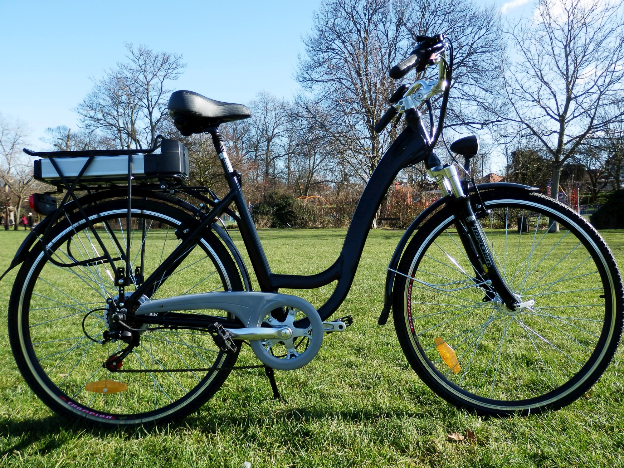
The Woosh Aspen (now replaced by the Santana2) :
http://wooshbikes.co.uk/?aspen
We still keep parts for the Aspen.
Can you post a picture of the damaged part or parts?
The Woosh Aspen (now replaced by the Santana2) :
http://wooshbikes.co.uk/?aspen

Thanks for that. The front part of the battery box has been broken around the lock and the lock (made of monkey metal inside) is trashed, the casing seems a bit thin where the lock sits in & I wouldn't trust that to stop someone stealing the battery though it would be no use once they got it out. I sent a message through your site as I couldn't see a spares section. I also need a wiring diagram as shorting the now broken ignition and plugging it back in produces no life at all though the batt is fully charged. (the battery was ok apparently before this idiot got hold of it)Hello Barney2,
We still keep parts for the Aspen.
Can you post a picture of the damaged part or parts?
The Woosh Aspen (now replaced by the Santana2) :
http://wooshbikes.co.uk/?aspen
tech support does not work weekends. You'll have to wait until Monday.
If you want to do something in the mean time, test the battery voltage.
The lock has a rotating switch behind the cylinder, you'll see the red 36V wire going through the switch. You can detach the switch from the lock and turn it with a screwdriver.
Check with a voltmeter that the switch itself still works.
Please note that we can only support you if you could prove that the bike has not been stolen.
Hi. I removed the duff lock & turned the switch on manually. There's over 40V available unloaded. I'll get a receipt from the last owner.tech support does not work weekends. You'll have to wait until Monday.
If you want to do something in the mean time, test the battery voltage.
The lock has a rotating switch behind the cylinder, you'll see the red 36V wire going through the switch. You can detach the switch from the lock and turn it with a screwdriver.
Check with a voltmeter that the switch itself still works.
Please note that we can only support you if you could prove that the bike has not been stolen.
Cheers
Nopedoes the 790 LED panel light up when you press the on/off red button?
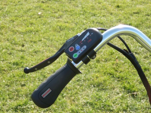
You need to check the wiring next.
Follow the cable from the 790 LED panel.
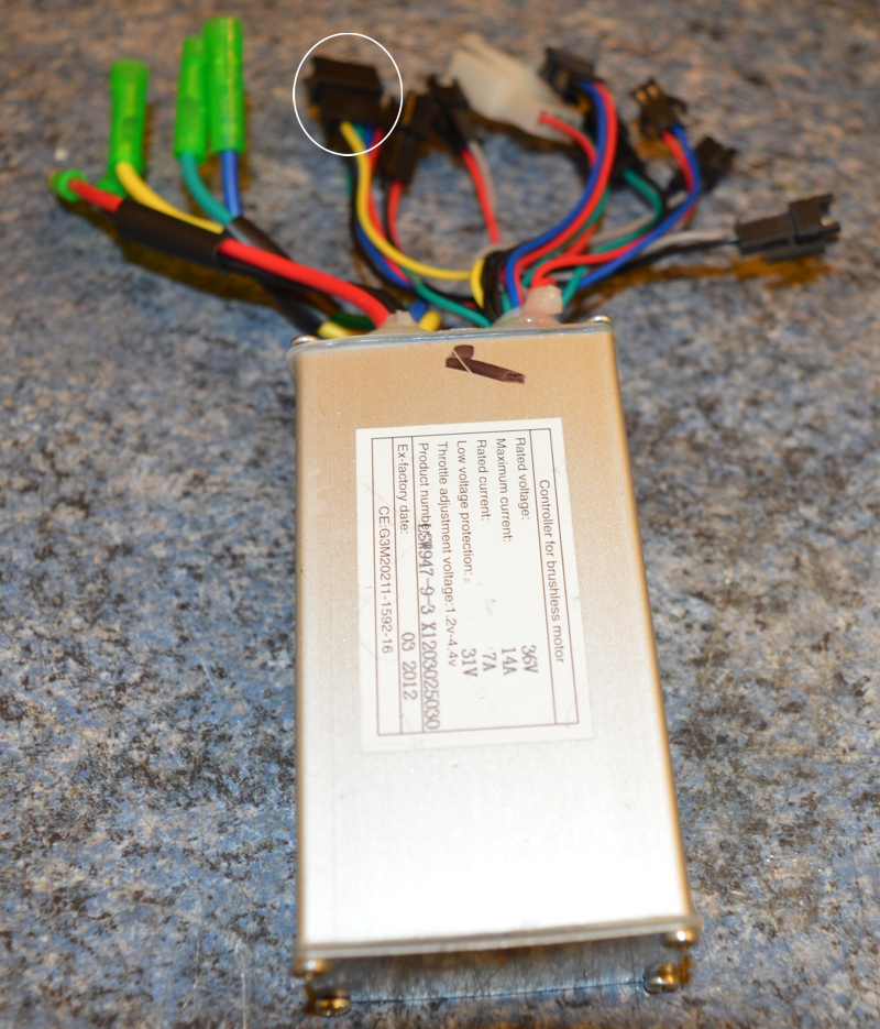
It should to go a black 5-pin JST plug. I circled it for you.
Make sure that the cable is still intact.
Follow the cable from the 790 LED panel.
It should to go a black 5-pin JST plug. I circled it for you.
Make sure that the cable is still intact.
Hi. I'm back on this again now.
The wiring was a mess, some plugs didn't seem, to go anywhere, I'm going to need a diagram to make sense of it, can you supply one or know where I can get please.
A parts list would be handy as well.
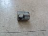
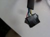
I've misplaced the bloody battery at the mo but I'll need an end housing and lock for that. Also the surround that holds the connector pins in place, a fitting for the carrier stay and 2 bolts for it (fitting pictured, bolts not as it was botched, anything else that goes with that part as well such as grommets if fitted, as I can see the bolts have 2 functions and length is critical. I've got a receipt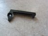 from the previous owner and can scan if needed.
The wiring was a mess, some plugs didn't seem, to go anywhere, I'm going to need a diagram to make sense of it, can you supply one or know where I can get please.
A parts list would be handy as well.
I've misplaced the bloody battery at the mo but I'll need an end housing and lock for that. Also the surround that holds the connector pins in place, a fitting for the carrier stay and 2 bolts for it (fitting pictured, bolts not as it was botched, anything else that goes with that part as well such as grommets if fitted, as I can see the bolts have 2 functions and length is critical. I've got a receipt
from the previous owner and can scan if needed.Hello Barney2,
We still keep parts for the Aspen.
Can you post a picture of the damaged part or parts?
The Woosh Aspen (now replaced by the Santana2) :
http://wooshbikes.co.uk/?aspen
Attachments
-
 1.2 MB Views: 16
Barney,
The broken piece of plastic looks like part of the plastic controller box.
The nut seems to be part of the mounting arm for the rear rack.
You really need to contact support by emailing support@wooshbikes.co.uk
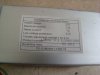
For second hand bikes, we need the invoice number to identify exactly what bike you have bought and the care history of your bike.
The broken piece of plastic looks like part of the plastic controller box.
The nut seems to be part of the mounting arm for the rear rack.
You really need to contact support by emailing support@wooshbikes.co.uk
For second hand bikes, we need the invoice number to identify exactly what bike you have bought and the care history of your bike.
Barney,
The broken piece of plastic looks like part of the plastic controller box.
The nut seems to be part of the mounting arm for the rear rack.
You really need to contact support by emailing support@wooshbikes.co.uk
For second hand bikes, we need the invoice number to identify exactly what bike you have bought and the care history of your bike.
Yep, I know what bit it is, I included the picture so you could see. I spoke to Andy today. He's emailing me a block diagram sometime (hopefully by tomorrow as I need to sort the wiring and order the parts). Did you see the attached picture of the carrier stay part? Cheers
Thanks. Andy was going to send me an email to davecarrick@gmail.com with a block diagram. No email yet, can you give him a nudge please, I need to get it fixed.Barney,
Andy is your man.
Cheers
I will. He is very busy today because Hatti is on holiday until Tuesday.
If you post a picture of your current wiring and questions, I should be able to answer them.
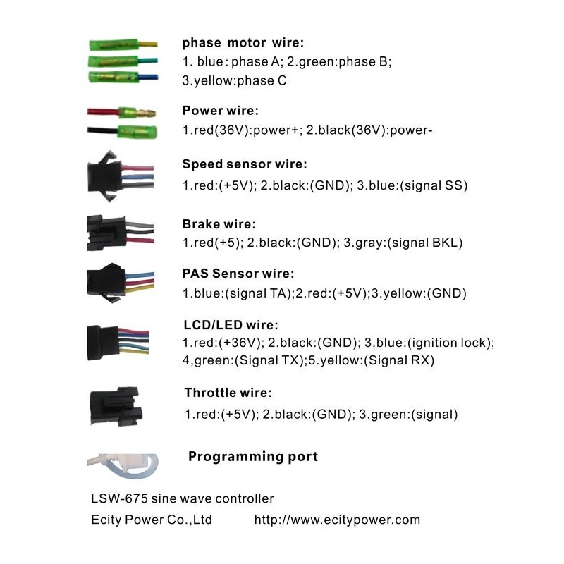
The Aspen uses the widely available Lishui LSW947 controller.
If you post a picture of your current wiring and questions, I should be able to answer them.
The Aspen uses the widely available Lishui LSW947 controller.
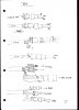
Ok, but this could get long-winded. The wiring is a mess, with disconnected plugs, some connected where the colours don't match, some repaired badly in the past. etc, I'll scan a drawing I made & send itBarney,
Andy is your man.
Here's the sketch I made of the connections as I found them.
Cheers
Cheers
Attachments
-
 455.2 KB Views: 20
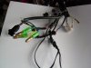
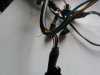
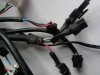
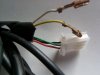
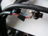
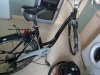
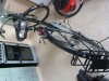
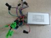
Pics of bike end attached. I think all of the controller plugs are fine.
Cheers
Cheers
Attachments
-
 1.2 MB Views: 15
 -
 1.2 MB Views: 13
 -
 1.3 MB Views: 12
 -
 1.2 MB Views: 11
 -
 1.3 MB Views: 11
 -
 1.2 MB Views: 11
Barney,
from your pictures:
This is my educated guess:
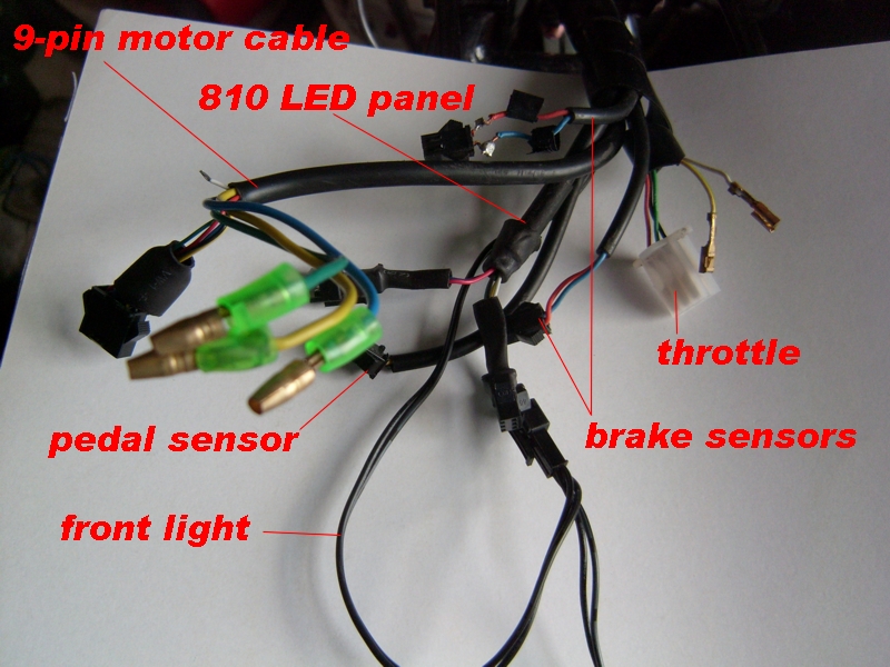
from left to right, the first cable, 9 wires with the white unused, is the standard 9-pin motor cable.
Its 9 pins are:
3 phase wires: large yellow green blue with 3.9mm bullet crimps
5-pin female JST connector are the hall wires
the white unused wire is reserved for the speed sensor.
The two red and blue 2-pin female JST connectors are the brake sensors.
The damaged JST connector should be replaced with a new one.
If the wires are shorted, the motor will be cut off.
the two pairs of black wires are for the front light. There is a switch on the 810 LED panel that turns the front light on/off. You must have 40V bulb to connect to these wires. Don't use them otherwise. The other two JST connectors (2-pin red and blue + 3 pin white, yellow, black) are for the 810 LED panel.
The white plug with red green black wires cable is the throttle.
I guess the white and yellow wires from the same cable can be on/off switch for the throttle.
There is a female 3-pin JST that is half hidden beneath the blue phase wire seems to be the pedal sensor.
Please post some pictures of your controller, I'll match up the wiring for you.
from your pictures:
This is my educated guess:
from left to right, the first cable, 9 wires with the white unused, is the standard 9-pin motor cable.
Its 9 pins are:
3 phase wires: large yellow green blue with 3.9mm bullet crimps
5-pin female JST connector are the hall wires
the white unused wire is reserved for the speed sensor.
The two red and blue 2-pin female JST connectors are the brake sensors.
The damaged JST connector should be replaced with a new one.
If the wires are shorted, the motor will be cut off.
the two pairs of black wires are for the front light. There is a switch on the 810 LED panel that turns the front light on/off. You must have 40V bulb to connect to these wires. Don't use them otherwise. The other two JST connectors (2-pin red and blue + 3 pin white, yellow, black) are for the 810 LED panel.
The white plug with red green black wires cable is the throttle.
I guess the white and yellow wires from the same cable can be on/off switch for the throttle.
There is a female 3-pin JST that is half hidden beneath the blue phase wire seems to be the pedal sensor.
Please post some pictures of your controller, I'll match up the wiring for you.
Last edited:
Related Articles
-
 MTF Enterprises announces acquisition of EMU Electric Bikes
- Started by: Pedelecs
-
 Wisper 806T folding bike wins Which? ‘Best Buy’
- Started by: Pedelecs
-
 Sustrans calls for protected cycle lanes
- Started by: Pedelecs
-
 Amazon launch their first UK e-cargo micromobility hub
- Started by: Pedelecs
