Help! 2 wheels better than 4, when its not raining.

bob d

Finding my (electric) wheels
Oct 14, 2023
21
0
Hello out there,
Well I guess help is the motivation I have to be here and in the interests of keeping a long story short I'd better get on with it. I'm a retired engineer of sorts and I've been associated with 2 wheeled transport since my childhood. Push bikes, mopeds, small motorbikes and big motorbikes have carried me many a mile, and now in my retirement my desire to fix things (classic bikes) that don't work has become a bit of (a lot really) a hobby.
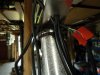
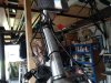
I've been watching the world of e-bikes for quite a few years now and have noted their technical development with some interest and so when recently offered a 20 plus year old Ezee Sprint in a non working condition I jumped at the chance to try my hand at renovating it.
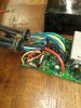
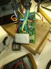
The mechanical and basic wiring stuff is'nt a problem for me but after finding and correcting several electrical faults and correcting them there is still not a flicker of life from the poor thing.
In the interests of maintaining originality I really don't to go down the route of fitting a new kit/system and so a helping hand (a clever electronics person) is needed to further this project.
The bike shops I've contacted so far have had no interest other than to try to sell me a new bike and have avoided talking technical.
So , here I am wondering which way to jump next and wondering what type of response this little story my get.
Many Thanks
bob d
 

saneagle

Esteemed Pedelecer
Oct 10, 2010
4,181
2,077
Telford
It might be easy to fix or not. In principle, any such ebike is easy to fix but Ezee used some non-standard parts.

To fix any ebike, this is how you check it with everything switched on that you can:
1. Measure the voltage at controller's battery connector. Obviously should be battery voltage. 36v - 42v for a 36v battery would be an acceptable range, but if you've fully charged the battery and it's less than 41v, it needs some sorting.
2. Measure the voltage on the 5v rail. You can measure that between any ground (black) and any of the reds going to throttle, PAS or motor halls. It should be around 5v.
3. Check throttle signal wire voltage on it's connector while connected. it's the wire that's not red or black on the throttle connector. Should give about 1v to 4v when you twist the throttle. If there's more than one wire, your meter will find it. It's the one that's between 1v and 4v, assuming that it works.
4. Check that the pedal assist sensor is pulsing. Measure the PAS signal wire while turning the pedals slowly. Should pulse 5v on and off every time a magnet passes the sensor. The signal wire is the one that's not red or black.
5. Check the motor hall signal wires (blue green and yellow) on the motor connector at the controller. They should each pulse with 5v going on and off as you rotate the wheel BACKWARDS.
6. Mosfet test. Disconnect the motor cable and battery from the controller. Measure the resistance (200k scale) between the red battery connection and each of the three phase wire connections, then repeat with the black battery wire. Each set of 3 readings should be the same as each other and in the range 7K -24K. Though can be higher as long as they're all the same. Due to the capacitor across the battery wire, you can get a constantantly changing measurement while it charges. In that case, try swapping your probes round. Even though can be a moving result, the only important thing is that all three move in a similar way.

If your bike passes all those tests, it should work, so then you can look at any settings or other logical causes, like stuck brake switches, PAS installed backwards.

When checking whether the motor will work, always disconnect all unessential connectors, like PAS (if you have a throttle), lights and brakes.

Once you know what the problem is, you can then find a way to fix it. One problem I encountered with an Ezee bike was that the motor wouldn't run very well with a different controller, which is a shame because the Ezee one is very old-fashioned, so it's function is crappy compared with modern ones, and they're very expensive as a spare part. That might have been just the one I had. the only reason I mention it is so that you don't rush out and buy a new controller hoping it will fix everything without testing.
 
Last edited:

bob d

Finding my (electric) wheels
Oct 14, 2023
21
0
Many Thanks to saneagle (I hope I have the name right) and the information I've received will be most helpful in due course which is now printed off and in my Ezee folder. However my previous post was incomplete as I was afraid of boring readers into nodding off and so I left out the second chapter of the no doubt familiar tale.
Chapter 2
Upon receipt of said Ezee Sprint I did a little investigative work and found a couple of badly frayed wires and a corroded snap connector. these problems were temporarily corrected and all the wiring and connections checked for continuity. I did a little research on the internet and managed to find some bits I could understand in the hope to re-educate myself and replaced the throttle as the Hall sensor wasn't working and checked the brake lever switches and the pedal assist sensor and all seemed to be working.
Now then, at 2 or 3 stages along the way I wanted to check to see if any of the faults I had found had made a difference but as the battery hasn't been charged for over 10 years and shows a reading of about 16 volts, and the charger is missing, I connected the bike to three 12 volt car batteries wired in series with a 10 amp fuse.
A big nothing was the answer, well almost nothing apart from a green light illuminating the battery condition monitor. Well I think that's what it is.
Next job was to take a peek inside the control box to spot any obviously cooked components. Well I didn't spot anything but a mate called in and had a look and noted that there are 2 or 3 components around where R21 and T2 is printed on the circuit board that definitely look a bit frazzled. Please see attached photo (a zoom is reqd).
So my next comment is that I reckon I need a new battery and charger and it would be good to get one that fits into the original Ezee plastic battery box (the 3 car batteries I borrowed are no longer available).
I've spotted a battery on Amazon that will fit but its 48 volt and I'm wondering if the system could cope with that.
It does seem like the battery issue might be a good place to start and an opinion on the control box is clearly needed.
That's where the conundrum is to date and once again I'm hopeful of an electronically minded kindly soul to point me in the right direction.
Many Thanks
bob d
 

Attachments

saneagle

Esteemed Pedelecer
Oct 10, 2010
4,181
2,077
Telford
The tests I indicated in my previous post will show you what's wrong. Don't start guessing. You'll just waste time and money. Use any 36v you can for testing. If it turns out you need a battery and controller, it'll probably be better to scrap the bike.

It's normal for that resistor to cook a bit.
 

thelarkbox

Esteemed Pedelecer
Aug 23, 2023
693
219
oxon
Good luck @bob d, hope you have a ball getting the old girl back on the rd, Cant help with your specific bike, but if our pal @saneagle suggests its a lost cause, could be time for a cup of tea and sit down before you make any decisions..

Avoid the 48v battery tho while over-volting motors is a thing afaik you need a suitable controller and could damage an unsuitable controller.

Probably best to get the 3x 12v batteries back in action until you have worked down the above tests.

If viable post the battery box dimensions for suggestions that could fit?..
 

saneagle

Esteemed Pedelecer
Oct 10, 2010
4,181
2,077
Telford
Just while I think of it, one common problem with those Ezee bikes is that the motor wires melt at the connector. Have a look inside that block thing that's on the front forks. If the wires melt far enough, they touch and can blow the controller.

Which wires were frayed?
 

bob d

Finding my (electric) wheels
Oct 14, 2023
21
0
Hi again and thanks for the help so far. I'll need to get hold of 3 car batteries again by the sounds of things and that will take a few days and so I wont be around until I get that sorted.
Another problem I'm having is with the site site and am struggling finding my way back to my thread. Any advice on that would be welcome.
Once again
Many Thanks
bob d
 

thelarkbox

Esteemed Pedelecer
Aug 23, 2023
693
219
oxon
Hi again and thanks for the help so far. I'll need to get hold of 3 car batteries again by the sounds of things and that will take a few days and so I wont be around until I get that sorted.
Another problem I'm having is with the site site and am struggling finding my way back to my thread. Any advice on that would be welcome.
Once again
Many Thanks
bob d
click on your profile name/pic (top right corner) and the 'your content' link will take u to a list of your posts..
 

saneagle

Esteemed Pedelecer
Oct 10, 2010
4,181
2,077
Telford
Hi again and thanks for the help so far. I'll need to get hold of 3 car batteries again by the sounds of things and that will take a few days and so I wont be around until I get that sorted.
Another problem I'm having is with the site site and am struggling finding my way back to my thread. Any advice on that would be welcome.
Once again
Many Thanks
bob d
Easiest way is to bookmark this page. if you use Chrome or Edge, you just click the little star on the left side of the adress bar.
 

bob d

Finding my (electric) wheels
Oct 14, 2023
21
0
Thanks again everyone and I have now re borrowed the 3 car batteries. They aren't new but each one will individually illuminate a 21W bulb and the the total accumulated voltage is 37 volts.
So, the first thing to report is regarding the 2 frayed wires which are 2 of the 6 that go from the controller to the battery condition indicator and pass through a bracket on the steering head and are the black and yellow wires. They could have both easily both been in contact with the steel bracket where they have frayed (picture attached).
Next bit was to start the test as described in the instructions and I checked the voltage on the wires going into the controller which were 37V. So far so good. Then I checked between a black wire and the red wire to the PAS and got 0.0V. Then I checked between a black wire and the red wire to the throttle and got 0.0V. Then I checked between a black wire and the red wire going to the motor Halls and got 0.0V. Then I checked between a black wire and the red wire going up to the battery voltage indicator and got 37V.
So, now I've established that (whatever that is) I'm wondering if the rest of the test is still meaningful although I will work my way through it.
Also there isn't a block connector of any type on the forks for the wires to melt in as they go straight from their connection at the controller to and into the front wheel spindle.
Many Thanks again
bobd
 

Attachments

saneagle

Esteemed Pedelecer
Oct 10, 2010
4,181
2,077
Telford
Thanks again everyone and I have now re borrowed the 3 car batteries. They aren't new but each one will individually illuminate a 21W bulb and the the total accumulated voltage is 37 volts.
So, the first thing to report is regarding the 2 frayed wires which are 2 of the 6 that go from the controller to the battery condition indicator and pass through a bracket on the steering head and are the black and yellow wires. They could have both easily both been in contact with the steel bracket where they have frayed (picture attached).
Next bit was to start the test as described in the instructions and I checked the voltage on the wires going into the controller which were 37V. So far so good. Then I checked between a black wire and the red wire to the PAS and got 0.0V. Then I checked between a black wire and the red wire to the throttle and got 0.0V. Then I checked between a black wire and the red wire going to the motor Halls and got 0.0V. Then I checked between a black wire and the red wire going up to the battery voltage indicator and got 37V.
So, now I've established that (whatever that is) I'm wondering if the rest of the test is still meaningful although I will work my way through it.
Also there isn't a block connector of any type on the forks for the wires to melt in as they go straight from their connection at the controller to and into the front wheel spindle.
Many Thanks again
bobd
No 5v means that either the controller isn't switched on or the 5vregulator is blown. It's unusual for a blown 5v regulator to be 0v. Normally, it gives out something.

Ezee electrics are a little unconventional compared with most Chinese bikes, though in principle they work the same.

The cable that runs from the controller to the display unit contains the wires that switch on the controller. One wire has battery voltage (probably red) and another is the switched wire that powers the controller. If you can find the switched wire, you can bridge them to test the motor.

Have a look and see if you can get all the colours in the cable. That might give a clue, otherwise you might have to look inside the controller to see where they go.
 
Last edited:

bob d

Finding my (electric) wheels
Oct 14, 2023
21
0
Much to my surprise I think I might be following this and can report back that the cable from the control box to the display unit has 6 wires. Yellow, red, black, blue, green and white, and if I take a reading between the red and any black wire I get 37v.
Also I've already got the control box cover off and can also report that the terminals that these 6 wires go to on the controller printed circuit board are marked as follows : yellow to SPD, red to KSI, black to GND, blue to IN, green to BRK and white to +5V.
Many Thanks again

bobd
 

saneagle

Esteemed Pedelecer
Oct 10, 2010
4,181
2,077
Telford
According to that info the switched wire is the blue. It used to be called the ignition wire, so IN looks about right; however the blue wire doesn't go to the right place on the controller PCB.

The way the wiring normally works is that a thin red is taken from somewhere nearby to where the thick red is soldered to the pcb, since they're just taking a branch off it. The red goes to the control panel (switch) and then comes back down the blue wire to land next to the burnt resistor. The power goes through the resistor to the 12v regulator, which is the upright three legged thing next to the resistor, then to the 5v regulator, which is the smaller three legged black thing standing in front of it. With a meter, you can follow the voltage along that path. In your controller, it's the red that lands near the resistor and marked KSI (Key switch ignition?). It's possible that that red flips over to the other side of the PCB and is joined to the blue there, and theres's another red that is connected to the battery wire and goes to the control panel. Check that out first. If that's it, bridge the red and blue wires to switch on the controller, then check again for 5v on the 5v red wires. If you get 5v, the motor should work with the throttle.

Note that Chinese normally mark the ignition wire KS for key switch.
 
Last edited:

bob d

Finding my (electric) wheels
Oct 14, 2023
21
0
Mmmm, I'm back again and a bit confused as your last message seemed to change. Not sure now whether or not I should continue and bridge the blue and red wires as first seem to be indicated.
I've been back and had another look and and the blue wire definitely goes to IN and have taken some photos of the controller PCB and the display unit PCB.
On the view of the controller PCB the blue wire in question is between the white and black wires and the views of the display unit are self exoplanetary.
Many Thanks

bobd
 

Attachments

bob d

Finding my (electric) wheels
Oct 14, 2023
21
0
Ah, I seem to have a new version of your last message.
I'll go and investigate a bit more.
Thanks Again

bobd
 

saneagle

Esteemed Pedelecer
Oct 10, 2010
4,181
2,077
Telford
OK, we need to go back a bit. I know that your controller is unconventional. It must be around 10 years since I looked at one, and things were different then. Since my last post and your pictures, I have a better understanding now. there is no switch to switch the controller on. It's always on when the battery is on. In that case, you only have to follow the voltage.

The red wire at KSI should have battery voltage on it. You can then check the 12v regulator is giving out 12v on the right leg as you look at it from the front, then check the 5v one. The input and output legs are the outer two, which can be either way round, so one should have 12v and the other 5v.

If you shorted the white to the black wire, then you shorted 5v to ground and it might have blown the regulator, which is an easy and cheap fix.
 

bob d

Finding my (electric) wheels
Oct 14, 2023
21
0
Hi again. Just back from another session with the mustimeter and there is definitely 36v at the red wire at KSI.
For the next checks I have assumed that I'm going between a black wire and the legs on the regulators to establish some readings.
So the readings from the large regulator read 0.6V on one outer leg and 0.3v on the other outer leg and 0.6 on the middle leg.
The smaller regulator reads 0.3v on each outer leg and 0.0 on the middle leg.
Many Thanks

bobd
 

bob d

Finding my (electric) wheels
Oct 14, 2023
21
0
Oh yes, I forgot to mention that I don't recollect trying to get any readings between the white and black wires.
 

saneagle

Esteemed Pedelecer
Oct 10, 2010
4,181
2,077
Telford
Oh yes, I forgot to mention that I don't recollect trying to get any readings between the white and black wires.
Maybe the resistor is blown after all. Check the voltage on each end. If the white wire was shorted, you overload both the resistor and the regulator. I've seen a lot of very brown resistors and the stuff around them, but I've never seen one blow. Maybe it depends how long you short them for.

You are measuring from ground?