OK here's what's rigged up might be easier to see.
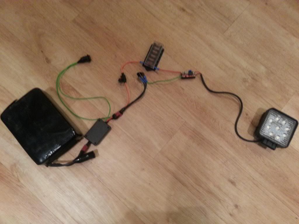
The master FET switch off the battery opens the circuit and closes it so I just use that to turn the light on and off.
The only contacts I have that aren't insulated are the BUSbar pins battery side of the DC-DC converter and the soldered wire contacts on the DC-DC converter itself (+ve / -ve IN pair and +ve / -ve OUT pair)
Perhaps best to just put the multimeter pins on either :
+ve in / -ve in
or
+ve out / -ve out on the DC-DC converter ?
So my guess is - assuming that current the light side of the DC-DC will be >200mA so use 10A range on multimeter, put pins on DC-DC out contacts and then open the switch ?
 to get some real readings