Alien conversion on a Peugot ladies tourer

chris_b

Finding my (electric) wheels
Feb 1, 2010
17
0
I promised I would post some pictures and notes of my progress through the modification of my daughter's Peugot ladies road/touring bike, so here it is. I'll start with some observations on the bike, the kit as received and then move on to the conversion job. Hopefully this will be interesting to current e-bike owners and useful to browsers and would-be kit buyers. The order of this monologue is roughly historic, but I'm taking the liberty of applying some hindsight to bring some things forwards in the story to a logical place (it also makes it look more like I think of *everything* ;) ). Posting is starting before we finish the job so please be patient...

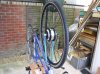
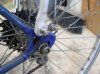
The bike was purchased in the mid 1980s (the deal was you get a bike to get to college for two years plus driving lessons, instead of a season ticket for the bus :D ). It has a steel frame and conforms mainly to French standards (thanks to Alex 728 for this link French Bicycles by Sheldon Brown which explains these). Wheels are 700C with 26 tyres, no room for MTB tyres so I checked the rim width with Alien before ordering - it's 25mm.

I picked the Alien kit after much browsing and lurking on fora such as this. On this forum in particular, I've had a lot of help and encouragement (Flecc and Old Timer, take a bow) even before starting in earnest. My spec is to assist my daughter up a 1.5 mile long 10 percent hill on her way to a new work site and a 36v 10Ah system is reckoned (by Alien and others) to be up to this. I also did some basic energy sums (and there are comprehensive spreadsheets on the web whic do it better) which imply that the energy from 60% of the charge in the battery is easily enough to lift her, bike and luggage up the hill. Time will tell!

The Alien kit arrived quickly and was well packed, nothing seemed to be missing or damaged. Runout at the rim of the wheel was under a millimetre as eyeballed with the axle clamped in the workshop vice and the rim sighted against a rule. Slight twitches of my eyebrows were been caused by:

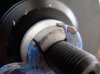
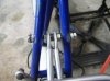
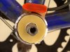
- two bits of the system don't look particularly waterproof, namely the battery charge socket and the connection between battery and controller box.
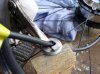
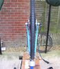
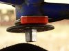
- the bunch of thin wires leaving the controller are hopelessly tangled for the first few cms. Whoever put the connectors on the groups of wires just couldn't be bothered to get the wires sorted first. Given the lack of space inside the box, being able to route these wires in their groups is a must and the tangle will make that difficult.
- the controller manual is hysterical. Joking aside, if there's anything of value in this publication, it's lost in translation.
- there's a dire warning at the end of the downloaded installation instructions about not plugging a charger into the battery if the charger is powered up. If it's that important, Alien should fit warning labels on the cable by the plug, and on the battery

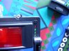
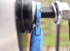
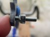
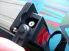
Here's pictures attached to illustrate the power connector


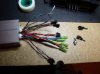
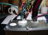
...and the tangle of wires...


Obvious (now!) issues, some to be solved by further application of wallet:

- the brake and throttle supplied with the kit are for 22mm handlebars. The bike has French-standard 23.5mm bars, so bars, stem and pin will have to be changed. Drops are going to be problematic in any case (the throttle goes where?), so conversion to straight is likely. Drop bar ends are available for these which may work (thanks Old Timer for finding these)
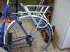
- a quick look at the carrier shows it's not intended for a bike with wheels smaller than 700C, so some modification/extension is likely
- the brake levers expect the cylindrical bullets on the ends of the brake cable inners, so inners will have to be changed


(to be continued...)
 

Attachments

Last edited:

chris_b

Finding my (electric) wheels
Feb 1, 2010
17
0
part 2...

Things I did first:

- charge the battery. It took three hours for the charger light to change from red to green. Given the warnings about not storing batteries discharged, it will be interesting to get a rough idea what three hours charging means in terms of the state of the battery as received. I will measure the real charging current at some point and estimate this.

- label the charger cable by the plug, and the battery

- cut the three unused connectors from the wires leaving the controller, tape the ends up and tape them out of the way on the side of the controller. Nb these connector require a special tool to remove the inserts, so leave a bit of wire coming out of the connector in case of future reconnection!. Threading these single wires though the rest enabled me to get rid of the worst of the tangle; I also twisted the groups of wires to make them easier to route.


- cut the unused connector from the unused wires on the battery connector and tape out of the way on the inside of the controller housing. WARNING: If you wish to take the connector out of the housing, mark it BEFORE you take it out of the housing as it can be installed either way round in the housing.


Question: Does anyone know the details of the leds on the battery (see photo), I guess they're a battery state indicator - all the green ones light when I press the tiny button and the red one doesn't. No mention in any documentation.....


Todo:
- think about waterproofing the joint between controller housing and battery. Initial solution is a reel of PVC tape and a weather forecast
- find a cap to put over the charge socket on the battery
 

Attachments

Last edited:

chris_b

Finding my (electric) wheels
Feb 1, 2010
17
0
Part 3 ...

Modifying the dropouts

This is the bit that requires care. The dropouts in the forks are 9mm and the axle on the Bafang motor is 12mm dia with 10mm flats so it requires 10mm wide dropouts. The motor comes with a pair of torque washers and it's important that these are snugly engaged in the dropouts to prevent the motor rotating. The motor cable leaves via the spindle so the washers and nut on that side are effectively captive because the cable has a large waterproof connector fitted. Not only are they captive, but you can't add any more washers unless you split them into a horseshoe.

When filing, the depth of the dropout is important 1) it must be deep enough for the torque washers to engage, 2) the depth of the two dropouts relative to each other sets where the wheel sits between the forks. Errors in 2) are magnified at the rim by a ratio of the wheel radius to half the axle width - in my case that's about 300/50 or a factor of 6. To get the torque washers to engage fully, the dropouts had to be 16mm deep. The wheel nuts are about 25mm diameter, so you require that depth of flat area for the forks. In my case, the nuts are about flush with the top of the fork (bike upside down), so 25mm is the size required for the flat area. For anyone reading this trying to guess if they have enough metal available to file away, be warned that another consideration is the fatness of the forks close to the dropouts as there's a real chance of fouling the motor (pictures below). Adding packing washers is one solution, but see the note re captive washers above.

Unless you are a wizard with a file (I'm not) it's difficult to do this filing. You can't get what you're filing rigidly clamped in anything and it's hard to judge the angle of the file which is a recipe for random removal of metal. My daughter and I filed each side of both dropouts together, a bit like using a two-handed saw. I got the handle and she got a pair of mole grips on the other end of the file. That way, at least the sides of the dropouts had a chance of remaining parallel. The geometry of the spindle is not straightforward as the arc at the bottom is part of a 12mm circle and nothing to do with the 10mm width. We took our time and did a lot of trial fits.

The photos show my end result. Not too pretty, but hopefully ok. I can see the torque washers move slightly if you rotate the wheel, but they are quite tight to get in so I don't reckon I could have done much better. The part of the torque washer that engages with the dropout must be just less than the thickness of the dropout so the wheel nut grips the dropout not the torque washer.

Dropout filed to size...


...both forks ready...


ISSUE No 1: We filed for equal depth of the forks and checked that the rim of the original wheel when placed in the dropouts sat central between the top of the forks. The new wheel was offset towards the left hand side of the bike (rider's view): left hand gap 10mm, right hand gap 21mm. After some headscratching I observed that the wheel is built like this. What to do? I tried a bit of manual fork bending but achieved nothing beyond a warm feeling that the slender forks are pretty stong. Then we tried packing washers on the left side (helpfully the side without the cable). Murphy's law applied: the left fork moved out, the right fork stayed put. This was a cold Saturday and wanting to make progress rather than wait for Monday and a call to Alien, I filed the left dropout bottom another mm. This centred the rim; the wheel will be off vertical by a small number of degrees and I'm hoping this won't affect the handling. Given how imprecise some of the rest of the bike is (see closeup photos of the dropouts which don't look to be at the right angle), I reckon to be in with a chance. Old Timer has subsequently checked his kit and his rim is central.

...clearance at left fork (two washers behind the torque washer)...


.. and at the right fork (yes I filed a a tiny flat on the fork)...


Attachments

Last edited:

chris_b

Finding my (electric) wheels
Feb 1, 2010
17
0
Part 4... Fork modification continued

You can see from the attached photos how the left dropout has been filed a bit deep, it has two washers fitted between torque washer and hub. The right is not quite deep enough for full engagement of the torque washer, but more depth would have meant the motor fouling the forks. No extra washer is used here as I didn't want to risk a horseshoe washer not staying where it's put.

Left fork ...


Right fork ...
 

Attachments

Last edited:

chris_b

Finding my (electric) wheels
Feb 1, 2010
17
0
Part 5...

Issue No 2: For some reason, the holes for the mudguard fixings are about 8.3mm diameter. With the motor fitted there is no room on the inside of the forks for the head of a bolt. Some searching in my fasteners stock turned up some countersink-head M5 screws which sit nicely flush. A nyloc nut fitted backwards has a lip that engaged nicely in the hole from the other side. Job done - see photo (in NRG's post below). At the rear of the bike, the holes were just over 5mm so I fitted some bolts there ready for the carrier.

Issue No 3: Drop handlebars, the supplied brakes with switches and twist throttles don't go together. Drop bar ends on a straight bar is one way to go, but I'd have to build special brakes for the drops as all the switched ones I've found are for straight bars, plus I'd have to sort bar cross levers etc etc. Drops is an extra for later. After some discussion, we've bought straight 22.2mm diameter bars, plus 22.2 stem/pin to suit. The French-ness of the bike may mean I have to remove 0.2mm from the pin and wedge. That will be a lathe job, though removal of metal with coarse emery paper would probably not be too hard

With couple of Marathon Plus tyres and a new chain, we're ready to start rebuilding.

(Short pause here as this is up to date now; hope to get outside tomorrow to finish the grubby cleanup bits, then negotiate to bring it indoors as it's a bit chilly out in the car-port and the workshop is too small)

Can anyone tell me how to add photos so they turn up in the text and not as attachments? - Sorted, thanks NRG
 

Attachments

Last edited:

NRG

Esteemed Pedelecer
Oct 6, 2009
2,592
10
Good job Chris, I reckon you've done well there. These kits are never going to be an easy fit as there's just too many bike variations about for a kit to cover them all. You can embed your pics by using the
tags like this:


I've not had any issue with water ingress yet on the charge socket but a cap is a good idea just in case....one thought on the clearance and perhaps I did not read it correctly could you not put another washer behind the fork to give a touch more clearance? Even with a part cut washer to slip behind the fork its not going anywhere when the nuts are tightened up....
 

Old Timer

Esteemed Pedelecer
Dec 5, 2009
1,279
12
Chris

Yeh! I had to fit my mudguard stay bolts from inside out with extra nuts to make the bolts semi permanet.
when i wired up the controller i said "it`s like putting a plate full of spaghetti into an eggcup":D
I had to file my fork drop outs as I said but luckily they were a perfect tight fit width wise for the spindle flats.

I did mention to one member who was considering a kit to look at the Alien Gents special bike for the extra money(£150) had i noticed that before I purchased the kit I think given the spec of the bike I might have gone down that road.

So! the connector to the front wheel is reversible? Noted.

You haven`t mentioned the pedelec yet, are you fitting it?

Keep it coming

Dave
 

chris_b

Finding my (electric) wheels
Feb 1, 2010
17
0
@NRG Thanks for the tip on images; I'll see if I can go back and edit. Yes, I could put a horseshoe washer behind the right fork, I was concerned it might not stay put. Also (from experience) as the right fork is "stronger" than the left, and adding washers there moves the wheel across in the direction I don't want! I confess to having filed a teeny-tiny flat on the fork to clear the hub.

@Old Timer - the connector I'm talking about is the exposed 4-pin one in the controller box that engages with the battery. I took it out as I wanted to bend the wires round inside at a tight radius to clear the controller and see if there's any waterproofing seal round it (there isn't)
 

john

Esteemed Pedelecer
Nov 1, 2007
531
0
Manchester
The part of the torque washer that engages with the dropout must be just less than the thickness of the dropout so the wheel nut grips the dropout not the torque washer.
This is very important, but the picture on this and your next post seem to show the torque washer protruding through to the other side of the dropout.

Although useful, torque washers only provide a small additional insurance against motor spinout, it is the friction provided by the nuts that is most important so these do need to be flush.
 

chris_b

Finding my (electric) wheels
Feb 1, 2010
17
0
@John - Quite right. That photo was taken before I reduced the height of the lug.

The next picture shows how I held the torque washer that is captive on the wire so I could file that one's lug down. I laid the wheel on the bench, taped the washer and nut out of the way (yellow tape in foreground) then fixed a wooden block to the bench and let it poke between two spokes. Now I could hold the torque washer with a pair of grips, support it on the block and file the lug down.


After that I could (at last) start reassembly; here it is with both wheels installed (plus two new tyres and a new chain).


A head-on picture looks ok - you can see the slight tilt in the wheel and how the left fork is further from the hub than the right fork.


Attachments

Last edited:

chris_b

Finding my (electric) wheels
Feb 1, 2010
17
0
Time to sort the carrier now. It seems the carrier is designed to suit bikes with smaller wheels/frames as the front fixings didn't reach the saddle stem pinch bolt which is the attachment place I've seen in most other examples.


Luckily there were two handy holes in the frame where the previous carrier was fitted and I was able to use those with a long setscrew, three nuts to clamp the carrier front supports and some homemade angled washers.


The rear supports have a length of solid bar that fixes to the frame by the axle and slides into the carrier rear support tubes. The bar has tapped holes for three heights (I used the top one), and the matching hole in the support tubes required some "moving" with a file to get it to line up. I had to "adjust" the bars as they didn't line up with the support tubes; a firm grip on the flat part of the bar in the bench vice and a tap with a lump hammer did the job.

The wire stays for the mudguards now fouled the support bars so I made some little plates to move them back about 15mm. With some jiggling around, I managed to get the carrier straight; once bolted up it feels pretty rigid.


Now I assembled the controller housing on to the battery support plate. The holes in the box required enlarging for the 5mm fixings supplied. Finally the plate is bolted to the carrier, checking that the battery slides in without fouling before the final tighten.

With the locking pin in the battery, I noticed that the battery doesn't fully engage in the controller. The pins in the connector are well engaged, so I'm not going to do anything to fix this. As another poster observed, the battery is going to rattle. I'll look into that.


I found the chinglish controller manual again when clearing the bench. Here's an example from the fault-finding section entitled: The battery can not be charged. In the adjacent column "process and means for check", it says "Check whether the voltage of the battery is up to the mustard or not". Really. You couldn't make this up.
 

Attachments

Last edited:

chris_b

Finding my (electric) wheels
Feb 1, 2010
17
0
The flat handlebars arrived so work continued. Installation of brakes and throttle was straightforward and the wiring was routed back to the controller. As this is a ladies-style frame rather than an MTB with crossbar, the main motor cable could do with being a couple of inches longer but we managed to get it to reach the controller housing with the outer insulation ending inside the housing (no entry for rain) by routing it away from the frame behind the seat tube.

The controller and wires were stuffed into the housing - untangling wires and cutting off the unused connectors (see first post) paid off and the stuffing wasn't too violent. The tiny screws that hold the housing lid on were discarded as it's impossible to get a screwdriver to them. The lid is currently secured with PVC tape.

With the bike reassembled apart from the pedelec, and held off the ground the motor was run on the throttle to check it's ok and that the brakes did indeed cut the motor off! All was ok so on to the pedelec.

We installed that on the left of the bike, with the sensor facing outwards


The disk with the magnets slides on to the pedal shaft with no location so we cut some rough washers from the lid of an ice cream tub and threaded a couple on to the shaft to keep the disk spaced from the sensor


By trial and error, we found that the disk should be fitted with the arrows against the usual direction of rotation


Attachments

Last edited:

chris_b

Finding my (electric) wheels
Feb 1, 2010
17
0
...and finally

A try up and down the road showed it all worked, so time for a serious test. There's a short sharp hill nearby - perhaps 150 metres long, so off we went, plus the camera. Here's the result


My daughter was pedaling that time and reached the top at about 11 mph without trying too hard. In fact the motor would pull her up without she pedals at all, with a final speed of about 4 mph! We were pretty impressed with that.

The first try on the real route to work om Monday was a success. To quote from her email

"Only took 11 mins to cycle here and had to stop for an ambulance [it was crossing her path - she didn't need it herself ;) ]. Was doing 13mph past the hospital slowing to 8 at the very top of the hill. Had to pedal as just the throttle struggled. Not too puffed out, battery on charge."

Well I promised assistance up the hill, not total carry-me capability :D . The battery indicators still showed three green leds out of three, and the charger took just 20 minutes to recharge. (Compare with three hours when I charged it on receipt from Alien)

Repeated today with no problems, and interest from a few of her colleagues! Some rain got her thinking about waterproofing the joint between battery and controller housing. Temporary fix was a piece of PVC tape from the lab at work. I think a waterproof bag is in the making.

So overall, we're very happy with the performance of the finished article. There were some wrinkles along the way, some because we were converting a road bike, and some where the kit could have been better (which I'll feed back to Alien)

I hope this thread is of use to someone searching to see what works and what doesn't, and maybe amusing to the old hands here. Thanks to all who offered help and advice, both in response to postings and via PM. We'll report back after a bit with a longer term view

Chris B
 

Attachments

Last edited:

NRG

Esteemed Pedelecer
Oct 6, 2009
2,592
10
Good work Chris, The Bafang with the Alien controller gives its best power if you don't let the speed drop below about 7~8mph, so don't let it struggle up hills as the available energy from the battery is being converted more into heat than forward motion....
 

muglewump

Just Joined
Feb 19, 2010
2
0
Update now the bike has been in use

Well I've now been using the bike for nearly 2 weeks and I think its great. Below are some pictures of the hill I have to go up every day.

Looking down the hill, you can see the 10% sign


Looking over the hill towards Portsmouth


Looking down the hill


Looking up the hill from near the bottom


Attachments

Last edited:

Old Timer

Esteemed Pedelecer
Dec 5, 2009
1,279
12
Time to sort the carrier now. It seems the carrier is designed to suit bikes with smaller wheels/frames as the front fixings didn't reach the saddle stem pinch bolt which is the attachment place I've seen in most other examples.


Luckily there were two handy holes in the frame where the previous carrier was fitted and I was able to use those with a long setscrew, three nuts to clamp the carrier front supports and some homemade angled washers.


The rear supports have a length of solid bar that fixes to the frame by the axle and slides into the carrier rear support tubes. The bar has tapped holes for three heights (I used the top one), and the matching hole in the support tubes required some "moving" with a file to get it to line up. I had to "adjust" the bars as they didn't line up with the support tubes; a firm grip on the flat part of the bar in the bench vice and a tap with a lump hammer did the job.

The wire stays for the mudguards now fouled the support bars so I made some little plates to move them back about 15mm. With some jiggling around, I managed to get the carrier straight; once bolted up it feels pretty rigid.


Now I assembled the controller housing on to the battery support plate. The holes in the box required enlarging for the 5mm fixings supplied. Finally the plate is bolted to the carrier, checking that the battery slides in without fouling before the final tighten.

With the locking pin in the battery, I noticed that the battery doesn't fully engage in the controller. The pins in the connector are well engaged, so I'm not going to do anything to fix this. As another poster observed, the battery is going to rattle. I'll look into that.


I found the chinglish controller manual again when clearing the bench. Here's an example from the fault-finding section entitled: The battery can not be charged. In the adjacent column "process and means for check", it says "Check whether the voltage of the battery is up to the mustard or not". Really. You couldn't make this up.
Hi Chris

I wonder why you didn`t take the front rack support bars to the outside of the frame for a bit more stability:confused:
 

chris_b

Finding my (electric) wheels
Feb 1, 2010
17
0
Errrr, I can't remember but I think there wasn't enough movement with the slots on the carrier to get the supports outside the frame. There again, I might have just not spotted that it was a good idea :eek: