Alien Gents Special II - Improvments and Modifications

NRG

Esteemed Pedelecer
Oct 6, 2009
2,592
10
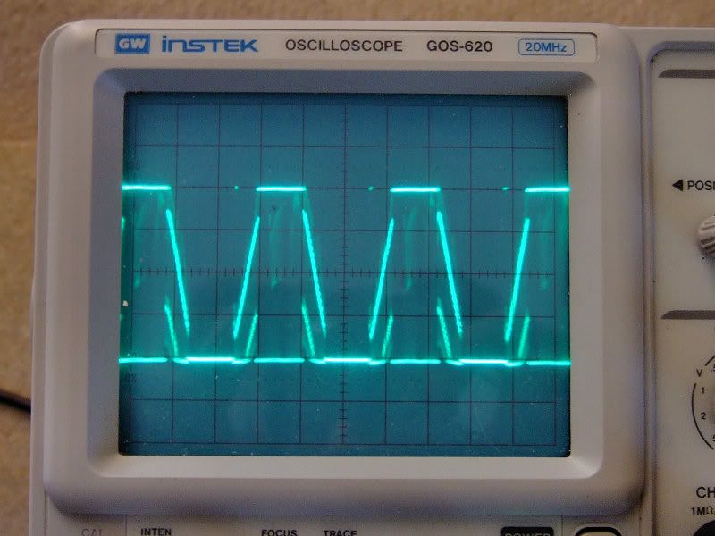
Wurly, that's good feedback and you 'scope shots are very similar to mine:

High, note the clean trace. vertical scale is x10 probe so 40v (VBatt) and 2ms / div horizontal.


The traces get progressively noisy and this has been reported on ES so it is to be expected. Medium power:


and low power:


So from your practical test it seems not only is the PWM signal being modified the frequency is as well. There is a really good thread on ES: Endless-sphere.com • View topic - **Important** reality check on motor, voltage, current etc. that goes into how these controllers work, however, there's a lot of chatter along with a lot of misinformation, I'm still working through the thread but so far not seen any mention of frequency...
 

NRG

Esteemed Pedelecer
Oct 6, 2009
2,592
10
Cable has arrived, now got to figure out how to connect it up, where to get the USB drivers from(!) and what the default controller settings are! :D
 

wurly

Esteemed Pedelecer
Aug 2, 2008
501
9
Yeovil, Somerset
Well i'm sorry to report that there is no increase in max speed by changing controllers. Reading the previous posts by jbond, i believe he is correct. Whether it is back emf, simply the motor has reached it's maximum speed because it cannot draw anymore current without increased voltage, i have no idea. It would have worked out nicely if it was simply down to the frequency of the PWM waveform. The only way i see now is to either change the gearing or go for 48volts.
Seeing that i'm already using a motor designed for a smaller wheel, i have a significant speed increase anyhow....i guess i should be happy with that.
Good luck with your controller NRG i'll be watching with interest.
 

jbond

Esteemed Pedelecer
Jul 29, 2010
411
2
Ware, Herts
www.voidstar.com
Wurly, Could you do me a favour and list out your highest speed combination. I think it's
- Tongxin 260 rpm hub (designed for 20" wheel?)
- 26" rim
- Dual mode 15A controller. From where?
- No load speed? Real world road speed?

The E-Crazyman controllers apparently don't have any mechanism for reading out their current settings. This makes initially flashing them with a set of values a bit of a shot in the dark unless we can find some stock values to work from. As NRG has found, they do seem to work straight out of the box so the stock values must be consevative and straight forwards. The speed control settings seem to be in four parts.
- A Limit speed. Not quite sure if this is a multiplier for the others or a limit. It's a latch set by a connection on the board. Seems to be aimed at a legal on/off switch.
- Mode style. Again, the descriptions don't make a lot of sense, but there's some sort of optional restriction on what modes are available.
- Three speed settings for low-mid-high. Each settable from 0-120%. People have successfully edited the software to allow setting up to 150%. It's not clear what values >100% actually mean. It's also not clear what the % is of.

Then we have the throttle input with it's nominal 1.2v -> 4.4v. Perhaps these % are % of 4.4v. So 113% is as if the controller had a 5v throttle input. Which then raises the question of what exactly the throttle input does. The software has no direct frequency setting, so logically the speed controls can only be proportions of duty cycle or max current. And yet the throttle also seems to be a speed/frequency limit. As NRG has found, the voltage is the same in all three modes so it's not a voltage limit setting the noload rpm at different voltages. This makes sense because the FETs are just chopping and switching battery voltage, not changing or amplifying it.

Still too many frequently unanswered questions here!
 

jbond

Esteemed Pedelecer
Jul 29, 2010
411
2
Ware, Herts
www.voidstar.com
Just realised something looking at those traces and especially Wurly's.
- no-load rpm is a function of motor wind and voltage in rpm/volt
- motor rpm sets controller frequency not the other way round.

<100% speed is achieved by chopping the waveform at a very high frequency. Much higher than the duty cycle. So in high mode 100% there is no chop and a clean trace. At 50% (low mode), there is the same apparent 100% duty cycle but this is overlayed with a very high frequency chop so the voltage is 0 for 50% of the time. So the average voltage is 50%. So the no-load rpm is 50%. So the observed frequency is then 50%.

This should correspond to 50% throttle in high mode. With reduced throttle settings introducing more and more chop to reduce the average voltage and hence the average no-load rpm.

Now, when I talk about the duty cycle of 100%, this is for one phase during the time when it's attracting the magnet. So on the scope you should see 100% voltage for 1/3 of the time. Perhaps values above 100% widen this or shift it's phase so you get an extra bit of push at the expense of some overlap with the other phases.

There's a bunch of resistance, capacitance and inductance in all the circuits, which I think explains the dirty traces in NRG's pics. It's Wurly's 2nd trace that gave me this idea.

Going back to what this means for performance. For a given motor and battery voltage, upgrading the controller won't give you any more speed, providing both controllers have a top speed setting of 100%. But a higher current limit will drive the motor harder below this speed. It'll get closer to it's max speed and give you more acceleration and hillclimbing. So, at 50% speed but 100% duty cycle and 100% voltage, the current limit is in effect. double the current = double the power.
 

jbond

Esteemed Pedelecer
Jul 29, 2010
411
2
Ware, Herts
www.voidstar.com
See here, where Jeremy explains it all.
Endless-sphere.com &bull; View topic - Keywin E-bike Lab Parameter Designer Software Manual-ver 1.2
Key facts.
- PWM Switching frequency is 15Khz.
- 100% means no PWM switching. 50% means 50% off at 15Khz superimposed on the phase signal.
- It's all multiplied so 50% throttle voltage times 30% low speed setting = 15% PWM.[1]
- A max current circuit reduces the PWM duty cycle to keep the current draw under the limit.
- Some 3-speed controllers come set up for 2 speed and speed 2 may not be 100% This all seems to be in aid of legal max speeds for a given motor.

[1] So when I'm riding over tree roots in the muddy woods in low mode with the throttle, I was doing the right thing because the throttle becomes less sensitive.
 

NRG

Esteemed Pedelecer
Oct 6, 2009
2,592
10
Yes I had worked this out but I'm not sure about the 15khz PWM signal, I'd like Jeremy to clarify that point.

100% is not 100% duty cycle, these controllers don't get to that as measurement shows, going above 100% setting switches off PWM and enables block communication mode as Jeremy points out it also disables over current protection as my tests today proved. I don't understand your third point, 50% speed setting scales the throttle control to provide half of 100% speed setting, read the ES thread I linked to previously.

Anyhow update is programming works, some interesting results today with various settings but anybody looking to gain extra speed from programming need to re- think as it appears the only practical way is to up the voltage...more tomorrow.
 
Last edited:

wurly

Esteemed Pedelecer
Aug 2, 2008
501
9
Yeovil, Somerset
Yesterday i went for a short ride, my 'pub on the hill' route. On the way back i took note of some speed measurements.

My current setup is a standard no name/no label 36V 250W sensorless dual speed controller as recieved from evassemble.
A 260rpm Tongxin hub (meant for a 20" rim).
36volt 5ah ping Lifepo4
Marin urban bike with 48T chainwheel
Me, 52 years old.
I also have a current limiter (shunt resistor..adjustable throttle clamp...ammeter).
On the flat with me pedelling i get 22.1mph. On a slight downhill stretch, it can assist me to 24.6mph.
As speed in increases i can hear the freewheel clutch disengaging at approx 26-27mph. Current drops of rapidly at 23-24.6mph and so does the assistance(obviously).
I can acheive a nice steady 19mph with my current limiter set to a reasonable 4-5amp max. When i get to a steep hill i set it at minimum, select a low gear and plod up the hill with the hub motor giving gentle assistance and the current limiter working to give the motor around 5amp. I am not particularly interested in going up steep hills at 15mph, i think that just wastes battery power. As long as i reach the top without having to get off is ok by me.

However, if by releasing more power from the controller gains me a few more mph along the flat i'm all for that. Especially, as i want my Bafang hubs to be faster than they are the moment.
At the moment it looks as if controllers have a top limit governed by ?????. I guess this is the what we are trying to get around.

One thing i have noticed is at low speeds my controller seems to be allowing the motor to draw more current than the my Tongxin controller giving my current limiter set up problems. No smooth control anymore. A modification needed i think.

Next experiment is to put a Bafang hub in my bike and see how it performs.
Personally i think to gain more speed it is down to gearing. My next bike will be a crank driven set up.
 
Last edited:

jbond

Esteemed Pedelecer
Jul 29, 2010
411
2
Ware, Herts
www.voidstar.com
Before you swap motors, can you check the no load rpm (wheel off the floor) in high mode.

What you've got there is very close to what I'd like to achieve. An assist speed limit that is above what I'm likely to achieve in a nice fast road bike. And then to limit current/power so that I'm mostly pedalling and the motor is just there to wind me up hills fairly slowly and to push up my average speed. What I'm researching at the moment is the lightest, lowest drag motor (with good reliability) that can achieve this. The choice is coming down to the TongXin, the smaller Cute and the SWXH/K Bafang. With a 20" wind/gear laced into a 26" or 700c rim. I can't quite decide about the merits of going to 48v. It should give a higher top assist speed but at the cost of more battery weight.

The Shengzen controllers don't allow the current limit to be adjusted on the fly. But somebody on here had worked out an adjustable current limiter that measured current with a CycleAnalyst style inline shunt and then adjusted the max throttle available to keep the current draw within a limit.

Then there's the whole throttle-pedelec-cruise issue. I find myself using the pedelec like a cruise control, and only using the throttle for fine control in town and in the woods. But that means I could just as easily use a cytronex style on-off button instead of the pedelec.
 

NRG

Esteemed Pedelecer
Oct 6, 2009
2,592
10
OK latest update:

Here's the controller connection points for reference. Older boards seem to have 5 connections the newer ones 6 like mine. This controller is from my Peugeot setup, Bafang motor laced into 700c wheel.


Not sure of the orientation of Tx/Rx, however, just follow the E-Crazyman cable wiring and all will be good. The PCB traces lift easily if too much heat is applied as I found out. I wired in a flying lead programming port to make things easier.


Cable, includes momentary switch to enable programming. USB lead is based on the Prolific TTL chip and the driver is linked to in a post above.


wurly

Esteemed Pedelecer
Aug 2, 2008
501
9
Yeovil, Somerset
Jbond
26.1 mph no load speed(as posted earlier)
Don't go for Tongxin unless you have a box of spare parts, good motors apart from the reliablities issues.
Is this the thread you were looking for?
http://www.pedelecs.co.uk/forum/electric-bicycles/4263-tongxin-current-limiter.html

I think you should also get on ES and ask the question what speed can i achieve running a Bafang at 48V they would have more idea. I have read they are ok up to 56Volts and then the nylons gears give up. As you know, the more speed the more power required, so i think the idea of current limiting may not even come into the equation.
 
Last edited:

NRG

Esteemed Pedelecer
Oct 6, 2009
2,592
10
E-Crazyman responded to my question about defaults and promised to send them over so while I wait I tried some out.

These are the settings in Parameter Designer that I ended up with yesterday. More experiment is needed as I'm concerned about the phase current.


The meaning of these settings can be found over on ES: Endless-sphere.com &bull; View topic - Keywin E-bike Lab Parameter Designer Software Manual ver 1.2

A brief run through on the settings of interest....

Select your board type, this version of the PD s/w is for the 116 controllers, the Infineon 8xx series is catered for in another version.

The key settings are Phase and rated current. Rated Current sets the maximum draw from the battery and offers a crude current limiter to protect your battery if it has a poor discharge rating or if you use a BMS with current limitation.

The Phase Current is the so called 'current multiplier'. At partial throttle under PWM conditions each phase of the motor will see a higher current than is drawn from the battery, this is due to the way PWM and the throttle works: Power in roughly equals power out/work done minus losses, if the voltage is halved to the motor then the current doubles to maintain the same power. The setting offers a crude way to limit this current, the recommendation on ES seems to suggest that this is set to 2~2.5x the rated current, however, they seem to be using low RPM direct drive motors.

For the Bafang motor I have my suspicions that this is too high as I found the controller getting noticeably hot even on a short ride, 1.5~2.0x maybe better.

Voltage limit sets the controller Low Voltage Cutoff(LVC). The 20% shifted figures in the ES link above are for the older 8xx controllers and only apply to the high current/voltage modified ones, standard controllers use the PD s/w settings as is.

Tolerance is how much the batt voltage needs to recover by after LVC is hit.

EBS is to do with Regen voltage, not possible with the geared Bafang motors.

Block time removes the current limiting for X number of seconds for fast take off.

1:1 Design changes the way the Pedelec works, Fast = crank / pedal rotation noticed quickly and motor cutoff after crank pedal has stopped takes a number of seconds. Slow = crank / pedal rotation takes a while to get noticed but motor shuts off quickly when rotation has stopped.

Limit speed works in conjunction with Speed2. Speed2 is the default speed setting if no 3 way switch is installed.

Speed1 = Low, speed2 = Medium, speed3 = High

Speed mode afects the operation of the 3 way switch. Switch mode = change speed settings on the fly whilst riding, Cycle mode = switch setting only read when controller is first powered on, so to change setting you must cycle the controller power.

Setting the speed1/2/3 to over 100% switches off current limiting and puts the controller into block commutation mode. I set speed3 to 110% and found that the current draw from the battery was unlimited noticing a 27amp peak draw on my short test route. At 100% it was limited to 20amp or so as per the setting. At 110% in high mode I gained approx. 1.5mph more speed with pedal assistance, the down side is the increased Wh / mile and stress on the controller. More testing later today if I get the chance.
 
Last edited:

NRG

Esteemed Pedelecer
Oct 6, 2009
2,592
10
Just received the default settings for the 20amp controller from E-Crazyman and I was only 1 amp out on the Phase Current setting. I still think its too much and I'm going to tweak both settings down to 18/36amp to see if there is any noticable difference.
 

John L

Esteemed Pedelecer
Nov 23, 2007
287
6
Hi guys

I'm going to have to give some serious time to catch up with all the posts :) Even if we cant get any extra top end speed I like the idea of being able to set up the controller to suit how I use the bike.

Once I get my new battery from Sunlova (hopefully next week) I'll be on to ecrazyman - if nothing else I'm looking forward to getting the pedelec sensor set up.

Thanks again for posting the results of ye're experiments.

John
 

jbond

Esteemed Pedelecer
Jul 29, 2010
411
2
Ware, Herts
www.voidstar.com
The key settings are Phase and rated current. Rated Current sets the maximum draw from the battery and offers a crude current limiter to protect your battery if it has a poor discharge rating or if you use a BMS with current limitation.

The Phase Current is the so called 'current multiplier'. At partial throttle under PWM conditions each phase of the motor will see a higher current than is drawn from the battery, this is due to the way PWM and the throttle works: Power in roughly equals power out/work done minus losses, if the voltage is halved to the motor then the current doubles to maintain the same power. The setting offers a crude way to limit this current, the recommendation on ES seems to suggest that this is set to 2~2.5x the rated current, however, they seem to be using low RPM direct drive motors.
Not sure about this description. Each phase gets power for roughly 1/3 of a revolution. So the average total current draw is 1/3 of the current for one phase while it's receiving power. I think the actual powered time is not exactly 1/3 and there is some overlap between phases hence the multiplier is a bit less than 3. Hence 2 to 2.5. I'm not sure if there's two shunts so that the average is directly measured across the battery feed and the phase current instantaneously across the feed to one of the phase FETs. If there's just one, then the ratio could be based on an instantaneous limit vs a smoothed limit. Perhaps there's some interaction here with speeds above 100%. In your experiment with 110%, the phase limit was still 45A but perhaps the width of the phases was increased with more overlap so the average and overlap peak current draw from the battery increased to 25A. I'd expect the processor to be sampling the voltage across the shunt and hence the instantaneous current very fast and often so it's the phase current that is probably most important. Or something.
 

NRG

Esteemed Pedelecer
Oct 6, 2009
2,592
10
Not sure I agree with that. The Phase current is a ratio of the rated current, the controller can only measure rated current via the shunt and has to guess/estimate the phase from this and the pulse width. The only way the controller can limit this current is via shortening the pulse whilst in PWM mode. To accurately monitor phase current would require a shunt in each phase.

Above 100% the controller is in block commutation mode no PWM and therefore no limiting, each phase in turn (there may be overlap, not sure) handles the battery current, its not averaged out over the three phases, it will flow into one and out of another controlled by the FET's.
 

jbond

Esteemed Pedelecer
Jul 29, 2010
411
2
Ware, Herts
www.voidstar.com
Goes off to think. Yup, I'm confused. From the ES thread DC current is what you'd measure on a cycle analyst. So that's the average current being taken from the battery. I'm not clear on what the phase current is though. Or how it can be bigger than DC current.
 

NRG

Esteemed Pedelecer
Oct 6, 2009
2,592
10
I think the ES guys likened it to a 'buck converter' if you had 10v at 10amp (100w) input then chopped the supply feed up with a 50% duty cycle the output, given no losses and the same load would be 5v at 20amp (still 100w). Obviously this only applies with PWM or in 'current limiting' mode.
 

jbond

Esteemed Pedelecer
Jul 29, 2010
411
2
Ware, Herts
www.voidstar.com
This is interesting Nanjing Lishui Electronics Research Institute Co.,Ltd. www.lsdzs.com It's about my controller rather than the E-crazyman controller but the feature set suggests the overall design is very similar.

Nanjing Lishui Electronics Research Institute Co., Ltd. www.lsdzs.com
3-speed mode refers to low speed mode, normal speed mode and hyper speed mode. Low speed mode only requires to limit the maximum output of motor, and the normal speed mode is the normal working state of motor. Whereas, the hyper speed indicates that motor can work well beyond its designed no-load speed (normally within 130%). Its working principle is to let three of the six MOSFETs turn on at the same time. (Under normal conditions, only two MOSFETs are turned on at the same time.) But this will lower the efficiency of motor for its not in the designed working state.

Nanjing Lishui Electronics Research Institute Co., Ltd. www.lsdzs.com
controller possesses multiple protective functions of current limitation. To ensure a high reliability, it not only limits the peak current cycle-by-cycle, but also limits the average current from the battery.
Also
Multiple current limits: Use average current limit and peak current limit. Peak current limit checks current peak at every PWM cycle and protect MOSFET from resistless peak current and avoid damage. Average current limit makes controller a const current limit performance on all motors at low load, medium load, high load or stall.

So maybe DC Current is the average current limit. And Phase current is the instantaneous peak current on a single phase when it's on during the PWM cycle. At low speed and low throttle angles, there's minimal back emf and during the 36V on part of the PWM, current will peak, even though averaged over the whole cycle, the PWM is more off than on and so the DC current is much less. So the phase peak limit is there as a protection for the FETs.